
Instruction manual
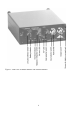

The supply voltage is connected to the terminals “+ 5 .. 15 V“ and “0 V”. A special plug with
screwed contacts for the rear socket is delivered together with the instrument. This way the
power supply can be wired manually. In case you use the offered 19”-mounting racks with inter-
nal power supply unit, this connection is realized by the backplane. Model M68R1 has no
power on/off switch.
The instruments are protected against false polarization and short-time excess voltage up to
60 V. All models of M68 series have an LED “BAT O.K.” indicating sufficient supply voltage.
It lights up green, as long as the voltage is above 5 V. It works for battery operation as well as
for external power supply (M68D1).
3.3. Battery Operation (M68D1)
Model M68D1 has a battery compartment for four “AA” size batteries (type LR 6). It is opened
by unscrewing four plastic knobs and removing the cover. The right polarity is shown on the
battery holder. To ensure long battery life it is recommended to use alkaline batteries. Accumu-
lators may be used as well. You can operate the instrument on NiMH or NiCd. However, by rea-
son of the lower voltage of accumulators, the battery control will not work exactly.
Please take discharged batteries out of the instrument to avoid damage by leakage. Also, remove
the batteries if the unit is not in use for a longer period.
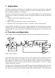
4. Inputs
The Signal Conditioners M68 are designed for both sensors with charge output and with inte -
grated impedance converters to IEPE standard as well. You can switch from one to the other
type of transducer by means of the slide switch next to the input socket. Both input types use the
same BNC input socket.
4.1. Charge Input
Capacitive signal sources, usually piezoelectric sensors with charge output, are connected to the
charge input (Q). The input is fed to an amplifier with capacitive feedback. All M68 instruments
have two input stages for charge. In the position “Q/10” of the switch the gain is divided by 10.
The advantage of charge measurement is, that cable capacitance and insulation resistance have
almost no influence to the measuring result. For sensors with charge output it is strongly recom-
mended to use special low-noise cables. Ordinary cable will cause a considerable measuring er-
ror at mechanical stress, as a result of the so-called triboelectrical effect. Cables with low insula-
tion resistance, for example caused by humid connectors, reduce the accuracy of measurement at
lower frequencies. A desirable insulation resistance is higher than 10 GΩ. Cables longer than
10 m are not recommended at the charge input.
4.2. IEPE Input
IEPE stands for "Integrated Electronics Piezo Electric". It has been established as industrial
standard for piezoelectric transducers. Other brand names for the same principle are ICP
®
, Iso-
tron
®
, Deltatron
®
, Piezotron
®
etc. The integrated sensor circuit transforms the charge signal of
the piezo-ceramics, with its very high impedance and high EMI sensitivity, into a voltage signal
with low impedance. The converted signal can be easier transmitted. The cable length at this in-
put may be more than one hundred meters. Ordinary low cost coaxial cable can be used.
7