
Instruction manual
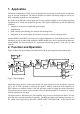


bandwidth down to 0.1 Hz comes into effect. The filters are followed by the second amplifier
stage. The divided gain before and after filtering provides sufficient dynamic range, even for si-
gnal components outside the filter range. At the same time a high signal-to-noise ratio is achie -
ved.
Before reaching the output driver the signal may pass one or two integrating stages. The output
is DC coupled.
A control LED for the output modulation indicates an output signal higher than 5 % of full-scale
modulation. An overload LED shows if the output signal exceeds 90 % of full-scale modulation.
It also indicates overload before the filter stages.
Models M68D1, M68D3, and M68R1 have identical electronic circuits.
3. Power Supply
3.1. Grounding Concept
The inputs and outputs of the signal conditioners are single ended, i.e. asymmetrical. In case an
additional signal ground connection is required, ground is available via a separate connector at
the rear of the instruments. For the Models M68D1 and M68D3 this connector is a 4 mm bana-
na jack. The signal ground of Model M68R1 can be found at the 4-pole frame connector.
The case of the instruments is internally connected to ground.
If model M68R1 is used with the rack cases M68B6 and M68B12 a connection is made between
signal ground and protective earth potential via the case.
The power supply is separated from signal ground. In some cases it may be of advantage to
connect the minus pole of the power supply to signal ground, to avoid ground loops. For this
purpose you can plug in the 4 mm jumper (delivered with the instruments) at the rear of Models
M68D1 and M68D3. At Model M68R1 the terminals of the power supply socket can be connec-
ted by a wire.
3.2. External Supply
The Signal Conditioners M68 are powered by an external DC voltage
Models M68D1 and M68D3 come with a mains plug adapter for 115/230 VAC. The power sup-
ply socket according to DIN 45323 is located at the rear of the instruments. Any other voltage of
5 V to 15 V DC and about 300 mA (for M68D1) or 1 A (for M68D3) may be connected to this
socket. The positive supply terminal is connected to center pin (tip). The POWER ON/OFF
switch is located at the rear.
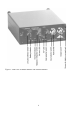
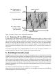
The M68R1 also has its power supply connector at the rear. It is a 4-pole frame connector type
WAGO 232. The pin designation is shown in Figure 3.
Figure 3: Power supply socket of Model M68R1
6
+ 5 .. 15 V
0 V
Signal ground
0 V