
Instruction manual


1. Application
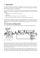
The Signal Conditioners of M68 series are intended for connection of piezoelectric acceleration,
force or pressure transducers. The input is suitable for sensors with charge output as well as for
IEPE compatible transducers or microphones.
By means of the M68 the sensor signal can be best possibly adapted to the existing measuring
equipment or PC-based data acquisition systems. The Signal Conditioners provide the following
functions:
• Adaptation of the sensor signal and sensor supply
• Amplification
• High- and low-pass filtering (for example anti-aliasing filter)
• Integration of the sensor signal, for instance, to measure velocity or displacement.
Models M68D1 and M68D3 are housed in a rugged aluminum case. Both models can be used in
laboratory as well as under field conditions. Model M68D1 may also be operated from batteries.
Model M68R1 has been developed for multichannel measuring systems. It fits into 19”-rack
systems.
2. Function and Operation
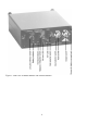
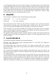
Figure 2 shows the block diagram of Model M68 with its most important functional groups.
Depending on the position of the input switch, the input signal passes the impedance converter
Q1 or Q2. If IEPE operation is selected, the signal is directly connected to the amplifier. At
IEPE
operation a constant current is fed into the input socket to supply the sensor electronics.
The constant current source can be switched off by the internal jumper J1, in case an AC voltage
shall be connected to the input.
The input circuit is followed by the first amplifier stage, low pass and high pass filters. The low
pass filter has 6 selectable limiting frequencies. The high pass filter has a limiting frequency of 3
Hz, which can be bypassed by the switch “HIGH PASS / INTEGRATOR”. In this case the full
5
Figure 2: Block diagram
U
Q/10
Q
U
Q/10
Q
Q1
Q2
IEPE
supply
J1 (ICPon/off)
Low pass
Frequency
High
pass
0.1Hz
3Hz
V2 1. Int. 2. Int.V1
Gain
a
v
d
Gain
Input
Overload
Output
IEPE
+
Compa-
rator
>5%
V=1
Compa-
rator