
Instruction manual
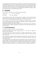


In some cases signal components with high frequency and magnitude may overload the ampli-
fier although no overload can be detected at the M68 output. The overload LED remains dark.
This can occur due to the attenuation of higher frequencies by the integrator (compare Figure 8).
To avoid possible overload, make sure to check the signal level in the switch position “ACC”
(integrator off) before using the integrator. If an overload condition should be indicated, reduce
high frequency components by an appropriate low pass frequency.
14
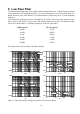
Figure 8: Frequency response of the integrators
100
10
1
%
dB
Hz
D
o
u
b
l
e
i
n
t
e
g
r
a
t
i
o
n
S
i
n
g
l
e
i
n
t
e
g
r
a
t
i
o
n
Modulation limits
Max.
modulation
0.1 1 10 100 1000
20
0
-20
-40
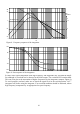
Figure 9: Pase response of the integrators
180°
-180°
0
90°
-90°
0.1 1 10 100 1000