
Instruction manual

A star-shaped grounding network is the ideal solution to avoid ground loops. Star-shaped means
that all grounding wires of the sensors and the amplifier outputs are tied to ground at the signal
conditioners, without any transverse connections. In many cases this is more difficult to realize
for the outputs than for the inputs, because the following measuring equipment may have single-
ended, inputs. If you have the choice to use differential inputs, which can be found on many
data acquisition boards, you should preferably use them.
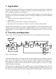
6. Amplifier
The instruments of M68 Series have the following measuring ranges:
Charge mode: 0.1 / 1 / 10 / 100 / 1000 mV/pC
IEPE mode: 1 / 10 / 100 / 1000 times
The gain selection switch ”GAIN” has four positions. In position “Q/10” of the input selection
slide switch the measuring range of all charge ranges is divided by 10. This may be advanta -
geous for measurement with high sensitivity transducers or for shock measurement.
After connecting a sensor and occasionally after changing the measuring range, the amplifier
needs a certain settling time because of a short term overload. Therefore it may take up to 30 s,
until the output voltage is free of DC components.
The amplifier output is buffered and DC-coupled. Therefore, possible offset currents fed into the
amplifier output by the following equipment (for instance a PC data acquisition board), do not
cause a DC offset.
7. Level Indicators
LEDs indicate minimum modulation and overload condition.
The LED “>5%” lights up at an output voltage higher than 0.7 V. The LED “OVL” lights up if
the output voltage exceeds 9 V.
The optimum gain range is selected, if the LED “>5%” lights up and the LED “OVL” remains
dark. If both LEDs remain dark, the gain should be increased. If both LEDs light up the gain
should be reduced.
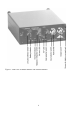
The overload detector monitors both the amplifier output and the filter input (see Figure 2). By
that means overload condition will also be indicated when high signal components beyond the
filter pass band occur.
An overload detector at the integrator input is not provided. In some cases high level com-
ponents at higher frequencies may overload the amplifier stage before the integrator while at the
integrator output no overload condition can be detected. To avoid this, make sure to check the
signal level in the switch position “ACC” (integrator off) before switching on the integrators.
When the LED indicates overload you can use the low pass filter to attenuate high frequencies.
10