Instruction Manual Charge Amplifiers M68 Series Manfred Weber Metra Mess- und Frequenztechnik in Radebeul e.K. Meissner Str. 58 - D-01445 Radebeul Phone +49-351-836 2191 Fax +49-351-836 2940 Email: Info@MMF.de Internet: www.MMF.
The latest version of this document can be downloaded from: http://www.mmf.de/product_literature.htm © Manfred Weber Metra Mess- und Frequenztechnik in Radebeul e.K. Aug.
Contents 1.Application................................................................................................................................5 2.Function and Operation.............................................................................................................5 3.Power Supply............................................................................................................................6 3.1.Grounding Concept................................................................
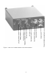
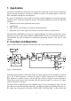
Figure 1: Front view of Model M68D1 with control elements 4
1. Application The Signal Conditioners of M68 series are intended for connection of piezoelectric acceleration, force or pressure transducers. The input is suitable for sensors with charge output as well as for IEPE compatible transducers or microphones. By means of the M68 the sensor signal can be best possibly adapted to the existing measuring equipment or PC-based data acquisition systems.
bandwidth down to 0.1 Hz comes into effect. The filters are followed by the second amplifier stage. The divided gain before and after filtering provides sufficient dynamic range, even for signal components outside the filter range. At the same time a high signal-to-noise ratio is achie ved. Before reaching the output driver the signal may pass one or two integrating stages. The output is DC coupled. A control LED for the output modulation indicates an output signal higher than 5 % of full-scale modulation.
The supply voltage is connected to the terminals “+ 5 .. 15 V“ and “0 V”. A special plug with screwed contacts for the rear socket is delivered together with the instrument. This way the power supply can be wired manually. In case you use the offered 19”-mounting racks with internal power supply unit, this connection is realized by the backplane. Model M68R1 has no power on/off switch. The instruments are protected against false polarization and short-time excess voltage up to 60 V.
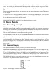
A peculiarity of IEPE is, that power supply and measuring signal use the same line. So, an IEPE transducer needs, like a transducer with charge output, only one single-ended line. Figure 4 shows the circuit diagram. To separate the low impedance sensor signal from the power supply, the integrated circuit is supplied with constant current. This constant current must be fed into the measuring line and simultaneously separated from the following amplifier stages.
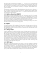
Max. output voltage = supply voltage of constant current source positive overload 24 V Sensor bias voltage 5 .. 14 V (see data sheet) Min. output voltage = saturation voltage (see data sheet) 0.5..1 V 0V negative overload Figure 5: Dynamic range of IEPE compatible transducers 4.2.1. Switching Off the IEPE Supply In some cases it may be necessary to switch off the constant current supply, in order to use the input for normal AC sources.
A star-shaped grounding network is the ideal solution to avoid ground loops. Star-shaped means that all grounding wires of the sensors and the amplifier outputs are tied to ground at the signal conditioners, without any transverse connections. In many cases this is more difficult to realize for the outputs than for the inputs, because the following measuring equipment may have singleended, inputs.
8. Low Pass Filter To eliminate disturbing noise or to comply with the Shannon theorem: “Signal frequency should be less than half of the sampling frequency”, it can be advantageous, to use a low pass filter. For higher accuracy in the time domain it is recommended to set the low pass at 1/10 the sampling frequency. The instruments of M68 series have 6 internal low pass filters. The scale at the positions of the filter switch “LOW PASS” is shows the 3 dB limiting frequencies in kHz.
9. High Pass Filter The M68 signal conditioners have a high pass filter with a lower limiting frequency of 3 Hz (3 dB). By means of this filter low frequency noise can be removed. Low frequency noise may occur, for example, by the influence of temperature transients to piezoelectric compression type accelerometers. The slope of the 3 Hz high pass filter is 40 dB / frequency decade. The 3 Hz high-pass filter is switched on by turning the “INTEGRATOR HIGH PASS” switch into positi on “ACC 3 Hz”.
Vibration acceleration a (without integration): a= uout G⋅Bua (a in m/s²; uout in mV; G in mV/mV; Bua in mV/ms-2) Vibration velocity v (single integration): v= uout ⋅10 G⋅Bua (v in mm/s; uout in mV; G in mV/mV; Bua in mV/ms-2) Vibration displacement d (double integration): d= u out ⋅100 G⋅Bua (d in µm; uout in mV; G in mV/mV; Bua in mV/ms-2) The equations above apply for IEPE compatible accelerometers.
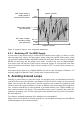
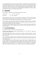
dB 20 Max. modulation % Modulation limits Sin gle 0 100 int eg rat i l ub Do on e 10 n io at gr te in -20 -40 1 0.1 1 10 Hz 100 1000 Figure 8: Frequency response of the integrators 180° 90° 0 -90° -180° 0.1 1 10 100 1000 Figure 9: Pase response of the integrators In some cases signal components with high frequency and magnitude may overload the amplifier although no overload can be detected at the M68 output. The overload LED remains dark.
11. Rack Cases for Model M68R1 For the 19” unit M68R1 the following rack mounting cases are available: Model M68B6 M68B12 Channels 6 12 Built-in power supply yes yes Figure 10: Front view of rack case M68B12 Figure 11: Rear view of rack case Model M68B6 The rack cases Models M68B6 and M68B12 supply the plugged-in modules via a backplane. They can be operated with both 115 VAC and 230 VAC without changing any settings.
The fuse holder of the rack cases M68B6 and M68B12 with mains power supply is located inside the mains socket at the rear. It can be pulled out using a screw driver. The fuse facing to the back of the drawer is a spare fuse. The rear one is the mains fuse. Important: Unplug the device from the mains voltage before replacing the fuse. Make sure that the fuse to be replaced has the rating T 800 mA. 12.
External supply 5 .. 15 VDC < 300 mA (M68D1, M68R1) < 1 A (M68D3) connector to DIN 45323 (M68D1 / M68D3) 4 pin frame connector (M68R1) Battery supply (only M68D1) 4 x “AA” size (LR6) > 10 h lifetime with alkaline cells Wide range input 85 .. 264 VAC Mains supply (only M68B6 / M68B12) Socket for IEC 320 mains cord Grounding required Power consumption: < 40 W Fuse: 800 mA (slow) in mains socket Mains plug adapter (only M68D1 / M68D3) Wide range input 100 ..
Limited Warranty Metra warrants for a period of 24 months that its products will be free from defects in material or workmanship and shall conform to the specifications current at the time of shipment. The warranty period starts with the date of invoice. The customer must provide the dated bill of sale as evidence. The warranty period ends after 24 months. Repairs do not extend the warranty period.
Declaration of Conformity Products: Charge Amplifiers Models: M68D1, M68D3, M68R1, M68B6, M68B12 It is hereby certified that the above mentioned products comply with the demands pursuant to the following standards: • EN 50081-1 • EN 50082-1 • EN 61000-3 • EN 60950 Responsible for this declaration is the producer Metra Mess- und Frequenztechnik Meißner Str.