
MK Battery Manual


g. Spray exposed terminals and connectors with several coats
of battery terminal corrosion protection spray. (Mask surround-
ing areas to protect against overspray.)
h. For batteries which may be exposed to very wet environments
(e.g. bilge mounted batteries) total encasement of the exposed
terminals and connectors is necessary. However, do not block
or cover the vents. Allow ventilation.
A battery terminal boot should be used. Install the boot on the
cable before crimping the terminal. Fill the boot with petroleum
jelly and fit over the sprayed connectors (as in “g” above).
i. Battery charging in a boat requires a charger specifically
designed for marine applications. In addition to battery gases,
bilges often contain potentially dangerous fuel fumes.
Follow all wiring and grounding recommendations of the
charger manufacturer for on-board and on-shore connections.
Using a charger not specifically designed for marine
applications or failure to follow the marine charger
manufacturer’s grounding and wiring recommendations
could result in major corrosion damage to the hull or
prop, and create a serious risk of electrical shock or fire,
personal injury or death.
Battery Installation
Note:
In a multi-battery installation, it is often best to replace the
entire set of batteries when one battery is weak or has failed.
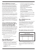
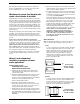
Series
A “series” system increases the voltage, but keeps the battery
capacity (cranking amps, amp hours, reserve minutes, and
minutes running time) the same. Therefore, two 12-volt
batteries connected in series (POS to NEG, NEG to POS)
will deliver 24 volts at the same rating as one battery:
During recharge, each battery receives the same amount
of current; e.g. if the charger is putting out 10 amps, both
batteries are getting 10 amps.
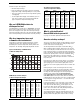
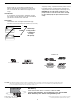
Parallel
A “parallel” system increases the capacity available, but keeps
the voltage the same. Therefore, two 12-volt batteries with
400 CCA, 110 R.C. and 65 Ah will deliver 12 volts, 800 CCA,
220 R.C. and 130 Ah. (Actually, since each battery’s load is
lighter, the reserve capacity will more than double.)
15
Also, when protected against short circuits and securely braced/
blocked, our VRLA batteries “are not subject to any other require-
ments of 49 CFR Parts 171-180…” for shipping.
Which way does current flow? On which side
should a circuit breaker be installed?
During discharge, electrons progress through the external circuit
from the negative post toward the positive post. Inside the battery,
positive ions move toward the positive plate by diffusion where they
react, leaving neutral molecules in solution. The resulting neutral
molecules move back toward the negative plate by diffusion. There
are also negative ions in the electrolyte offsetting the positive ion
charges. Some travel by diffusion toward both the negative and the
positive plates, where they are consumed. During charge, all of the
directions reverse.
Although not physically accurate, when designing circuits or making
calculations, it is just as valid to consider positive charges moving
through the whole circuit. Indeed, this is the convention used to
define the direction of current in electronics (known as conventional
current).
Proper location of disconnects depends on the application.
Vehicles can vary, but in most cases, the negative terminal is treated
as ground. The entire chassis is connected to the negative terminal
of the battery. The positive side of the circuit is considered “hot.”
Switches/circuit breakers should usually be installed on the hot
side of a device. When disconnecting the entire battery from the
system with a fusible link or circuit breaker, breaking the connection
from the negative terminal to the chassis often works best.
In multiple battery installation, there could be other considerations
such as total voltage, multiple voltages, and the effects on other
devices.
What do I need to know about
installation, especially in salt water
marine applications?
Wiring and Waterproofing
ALWAYS WEAR SAFETY GLASSES
WHEN WORKING AROUND BATTERIES!
a. Cabling of the approved gauge should be tinned copper.
If using untinned copper, allow plenty of spray silicone to
“wick” along the strands.
b. Install heat-shrink tubing with a silicone interior; the silicone
forms an excellent moisture barrier. Cut the tubing long
enough to cover the terminal lug and plenty of the insulated
portion of the cable. Slip tubing onto the cable.
c. Crimp on the appropriate terminal.
d. Position the heat-shrink tubing. Heat and inspect.
e. Clean battery terminals and connect. Be sure perfect metal-
to-metal contact is made, with no dirt, corrosion, grease or
foreign material to interfere with current flow.
f. Always attach the cable connected to the solenoid or starter
first. Attach the ground cable last! Tighten snugly, BUT DO
NOT OVERTIGHTEN, which will damage the terminals or crack
the battery cover. This will destroy the battery and VOID THE
WARRANTY.
Series hookup
increases voltage…
2 x 12V = 24 Volts
Parallel hookup
keeps same voltage…
2 x 12V = 12 Volts