
MK Battery Brochure

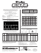

Capacity vs. Operating Temperatures: Above are the changes in capacity for
wider ambient temperature range, giving the available capacity, as a percentage of
the rated capacity, at different ambient temperatures. The curves show the behavior
of the battery after a number of cycles.
0%
2
0%
4
0%
60%
8
0%
1
00%
1
20%
-40 -30 -20 -10 0 10 20 30 40 50 60
Ambient Temperature (°C)
Percenatge of Available Capacity
The Deka Solar series of valve-regulated, gelled-electrolyte
batteries is designed to offer reliable, maintenance-free power
for renewable energy applications where frequent deep cycles
are required and minimum maintenance is desirable.
Applications
Water pumping • Residential • Communications
Cathodic protection • Remote monitoring • Refrigeration
Lighting • Aids to navigation • Wind generation
Specifications
Voltage …………… 12 volts nominal (8GGC2 is 6 volts)
Plate alloy ……… Lead calcium
Element, post …… Threaded stud or “flag” terminal, forged bushing
Container/cover … Polypropylene
Electrolyte ……… Sulfuric acid thixotropic gel
Vent ……………… Self sealing
Capacity vs. Operating Temperature
Terminal Information
The solar battery excels in cycling applications.
*Dependent upon proper c harging and ambien t temperatures.
Discharge Amps per unit to 1.75VPC at 77°F (25°C)
5 10 15 20 30 60 90 36820 24 48 100
Min Min Min Min Min Min Min Hr Hr Hr Hr Hr Hr Hr
8GU1 4,38,39,Y 12 74.7 54.3 44.6 38.8 31.9 21 15 8.50 4.67 3.56 1.58 1.33 0.73 0.36 23.4 (10.6)
8GU1H 4,17,38,39,Y 12 74.7 54.3 44.6 38.8 31.9 21 15 8.50 4.67 3.56 1.58 1.33 0.73 0.36 23.4 (10.6)
8G22NF 4,38,39,G 12 120 86.7 69.1 60 47 31.8 23.2 13.30 7.65 5.74 2.55 2.15 1.16 0.58 37 (16.8)
8G24 4,17,38,39,G 12 204 152 119 100 78 48.5 35 19.77 10.75 8.30 3.68 3.12 1.68 0.845 52 (23.6)
8G27 4,17,38,39,G 12 242 185.3 142.5 118.8 90.25 57 41.5 23.30 12.67 9.80 4.32 3.67 1.99 0.99 62.7 (28.4)
8G30H 4,17,38,39,B 12 266 199.5 161.5 137.8 104.5 64.5 47 26.20 14.20 11.00 4.88 4.10 2.15 1.08 69.5 (31.5)
8G31 4,17,38,39,X 12 266 199.5 161.5 137.8 104.5 64.5 47 26.20 14.20 11.00 4.88 4.10 2.15 1.08 69.5 (31.5)
8GGC2 4,38,39,G 6 325 250 210 180 150 99 76 45.30 25.80 20.00 9.00 7.60 3.90 1.98 68.4 (31.0)
8G4D 4,17,38,39,S 12 485 375 300 255 195 122 88 49.20 26.70 20.70 9.15 7.78 4.22 2.10 127 (57.5)
8G8D 4,17,38,39,S 12 600 460 370 315 245 150 105 60.60 33.00 25.50 11.25 9.54 5.18 2.65 157 (71.1)
LWH
7
3
⁄4 (197) 5
1
⁄8 (130) 7
1
⁄4 (184)
8
5
⁄1
6
(211) 5
1
⁄8 (130) 7
1
⁄4 (184)
9
3
⁄8 (238) 5
1
⁄2 (140) 9
1
⁄4 (235)
10
7
⁄8 (276) 6
3
⁄4 (171) 9
1
⁄4 (235)
12
3
⁄4 (324) 6
3
⁄4 (171) 9
1
⁄4 (235)
12
15
⁄16 (329) 6
3
⁄4 (171) 9
3
⁄4 (248)
12
15
⁄16 (329) 6
3
⁄4 (171) 9
3
⁄8 (238)
10
1
⁄4 (260) 7
1
⁄8 (181) 11 (279)
20
3
⁄4 (527) 8
1
⁄2 (216) 10 (254)
20
3
⁄4 (527) 11 (279) 10 (254)
Footnotes:
4-Gray Cover / Gray Case
17 - Includes handle
38 - “Non-Spillable” defined by DOT(Department
of Transportation) definitions
39 - “Non-Spillable” defined by ICAO (International
Commercial AirlineOrganization) and IATA
(International Airline Transport Association) definitions
B-Flag terminal w/ 3/8" diameter hole
G-Offset post w/ horizontal hole, stainless
steel 5/16" bolt & hex nut
S-SAE “automotive type” post
X-3/8" x 16" stainless steel stud posts
Y-Small L terminal with round holes
Batteries manufactured in polypropylene
cases and covers.
ALL RATINGS ARE AFTER 15 CYCLES AND CONFORM TO B.C.I. SPECIFICATIONS.
IMPORTANT CHARGING INSTRUCTIONS: WARRANTY VOID IF OPENED OR
IMPROPERLY CHARGED. Do not install in a sealed container. Constant under
or overcharging will damage any battery and shorten its life! Use a good
constant potential, voltage-regulated charger. The open circuit voltage of
a fully charged 12-volt battery is 12.8V at 68°F (20°C).
PH OT O VO LTA IC BAT T ER IES
Gel Cycle Life vs Depth of Discharge at +25°C (77°F)
Based on BCI 2-hour Capacity
10000
1000
5000
5
00
100
10%
Cycles
%
Depth of Charge
Cycle Chart applies to types with similiar design characteristics, ex., U1, 22NF, 24, 27, 31.
450
1
000
5700
600
2100
25% 50% 80% 100%
Gel Cycle Life vs Depth of Discharge at +25°C (77°F)*
Based on BCI 2-hour Capacity
Lyon Station, PA 19536-0147 • Fax: 610-682-4781
Domestic & International Inquiries Call: 610-682-3263
www.eastpennunigy.com • e-mail: sales@eastpennunigy.com
E.P.M. Form No. 0919 Rev. 3/09 © 2009 by EPM Printed in U.S.A.
All data subject to
change without notice.
No part of this document may
be copied or reproduced,
electronically or mechanically,
without written permission
from the company.
Domestic Inquiries Call: 1-800-372-9253
www.mkbattery.com • e-mail: sales@mkbattery.com
Photovoltaic Charging Parameters
B
ulk Charge Max Current (amps)
3
0% of 20 Hr Rate
Absorption (Regulation) Charge Constant Voltage 2.35 - 2.40 vpc
Float Charge Constant Voltage 2.25 - 2.30 vpc
Equalize Charge Constant Voltage 2.40 - 2.45 vpc
Temperature Coefficient 0.005 mv / °C
Cut-off parameters per charge & equalize intervals are application
s
pecific and will vary dependent upon site specific characteristics
such as temperature, days of autonomy, array to load ratio, ect.
Dimensions In (mm)
Approx. Wt.
Lbs. (Kgs.)
Volts
Footnotes
Type
No.
“
P O W E R E D F O R P E R F O R M A N C E
”
®
YG SBX