
Installation Sheet
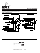
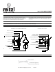
Table Of Contents
- ,HL111101G,
- GENERAL
- INSTALLATION TO OUTLET BOX
- STEP 1. Pull the wires out from the outlet box, and install mounting plate onto the outlet box using the (2) mounting screws.
- STEP 2. Fasten bare ground wire to ground wire from the wall outlet box (usually green or copper color) or connect ground wire to green screw on the mounting plate.
- STEP 3. Connect the neutral (white) fixture wire coming from the fixture base to neutral (usually white) outlet wire. Fasten both wires together with a plastic wire nut and tightly wrap the wire nut with electrical tape.
- STEP 4. Repeat the previous step with the hot (black wires). Make sure there are no exposed wires or strands that could cause a dangerous short circuit.
- FAILURE TO CONNECT THE APPROPRIATE WIRES CORRECTLY COULD RESULT IN SEROIUS INJURY OR DEATH!
- STEP 5. Carefully place connections back into the outlet box.
- STEP 6. Place Back plate over the mounting plate and secure with set screws.
- STEP 7. Screw in decorative plug into the bottom of the backplate.
- STEP 1. Lift glass shade up over the glass fitter and secure with thumb screws.
- STEP 8. Install the lamp(s). The fixture is rated for 60 watt G lamp.
- DO NOT EXCEED RECOMMENDED WATTAGE!
- STEP 9. Restore power to the circuit at breaker or fusebox.
- INSTALLATION USING STEM/PLUG
- STEP 2. Remove the mounting plate from the backplate
- STEP 3. Determine the location for the lamp. Using the mounting plate as a template, mark the location of the holes for the wall anchors.
- STEP 4. Drill the appropriate size holes for the wall anchors (holes should be slightly smaller than the size of the anchors).
- STEP 5. Install the wall anchors, and anchor screws.
- STEP 6. Install the mounting plate to the anchor screws using the key slot
- STEP 7. Attach stem to the bottom of the backplate, and feed cord through the stem.
- STEP 8. Connect the cord to the stem using the procedures outlined in steps 2-4 of the outlet box installation above
- FAILURE TO CONNECT THE APPROPRIATE WIRES CORRECTLY COULD RESULT IN SEROIUS INJURY OR DEATH!
- STEP 9. Place the fixture to the wall over the mounting plate and secure using the set screws.
- STEP 10. Lift glass shade up over the glass fitter and secure with thumb screws.
- STEP 11. Install the lamp(s). The fixture is rated for 60 watt G lamp.
- DO NOT EXCEED RECOMMENDED WATTAGE!
- STEP 10. Plug cord into a qualified socket of properly rated voltage.
- DIMMING
- CLEANING
- ASSEMBLY AND MOUNTING DIAGRAM
- WIRE NUT/TAPING DIAGRAM
- ,HL111 101G M40
- GENERALITÉ
- INSTALLATION À LA BOÎTE DE DÉRIVATION
- STEP 1. Retirer les fils de la boîte de dérivation et installer la plaque de montage à la boîte de dérivation au moyen des (2) vis de montage.
- INSTALLATION UTILISANT TIGE/FICHE
- STEP 6. Fixer la tige vers le bas de la plaque arrière et faire passer le cordon par la tige.
- STEP 7. Relier le cordon à la tige comme indiqué aux pas 2-4 de l’installation de la boîte à dérivation ci-haut.
- STEP 8. Placer le dispositif à la paroi sur la plaque de montage et sécuriser à l’aide des vis de fixation.
- RÈGLAGE D’INTENSITÉ
- NETTOYAGE
- SCHÉMA D’ASSEMBLAGE ET DE MONTAGE
- SCHÉMA DE BORNE DE RACCORDEMENT ET D’ENVELOPPAGE AVEC RUBAN ISOLANT

HL111101G RILEY SCONCE
www.hudsonvalleylighting.com/mitzi | #mymitzi
NOTICE D'ASSEMBLAGE ET DE MONTAGE
GENERALITÉ
•
AVERTISSEMENT - DÉBRANCHER LE COURANT AVANT DE
REMPLACER UNE AMPOULE OU DE RELIER LE DISPOSITIF AU
COURANT. COUPER INTÉGRALEMENT LE CIRCUIT
ÉLÉCTRIQUE AUQUEL LE DISPOSITIF EST RELIÉ.
•
L'INSTALLATION ET L'ENTRETIEN DE CE DISPOSITIF DOIVENT
ÊTRE REALISÉS PAR UN ÉLECTRICIEN AGRÉÉ.
•
UNE INSTALLATION INCORRECTE DU DISPOSITIF PEUT
ENTRAINER DES BLESSURES GRAVES OU LA MORT.
•
VEUILLEZ LIRE TOUTE LA NOTICE AVANT DE PROCÉDER À
L'INSTALLATION.
•
EN CAS DE REMPLACEMENT D'UN DISPOSITIF EXISTANT
RETIRER CELUI-CI ET NOTER À QUELS CÂBLES DE LA BOÎTE DE
DÉRIVATION LE DISPOSITIF ORIGINAL ÉTAIT RELIÉ.
•
AVANT DE JETER LA BOÎTE D'EMBALLAGE, CONTRÔLER
L'EMBALLAGE POUR S'ASSURER QUE TOUTES LES PIÈCES
ONT ÉTÉ TROUVÉES.
•
CE DISPOSITIF A ÉTÉ CONÇU POUR ÊTRE MONTÉ SUR UNE
BOÎTE DE DÉRIVATION OCTOGONALE. LA BOÎTE DOIT ÊTRE
FIXÉE DE MANIÈRE SÛRE À LA STRUCTURE DE L'IMMEUBLE.
INSTALLATION À LA BOÎTE DE DÉRIVATION
STEP 1. Retirer les fils de la boîte de dérivation et installer la
plaque de montage à la boîte de dérivation au moyen
des (2) vis de montage.
STEP 2. Fixer le fil de terre dénudé au fil de terre de la boîte de
dérivation à la paroi (généralement de couleur verte ou
cuivre) ou relier le fil de terre à la vis verte sur la plaque
de montage.
STEP 3. Relier le fil neutre (blanc) venant de la base du dispositif
au fil neutre (généralement blanc) de la boîte de
dérivation. Relier les deux fils entre eux à l’aide d’un
serre-câble en plastique et envelopper le serre-câble de
ruban isolant bien serré
STEP 4. Répéter le pas précédent avec les fils de phase (noirs).
S’assurer qu’il n’y a pas de fils exposés ou de brins qui
pourraient causer un dangereux court-circuit.
UNE CONNEXION INCORRECTE OU DES FILS
INAPPROPRIÉS PEUT ENTRAÎNER DE GRAVES
BLESSURES OU LA MORT!
STEP 5. Remettre soigneusement les connexions dans la boîte de
dérivation.
STEP 6. Placer la plaque arrière sur la plaque de montage et
sécuriser à l’aide des vis de fixation.
STEP 7. Visser le fleuron vers le bas de la plaque arrière.
STEP 8. Lever l’abat-jour de verre par-dessus le support de verre
et sécuriser par vis à serrage à main.
STEP 9. Installer la ou les ampoules. Le dispositif est prévu pour
des ampoules de 60 watt de type G.
NE PAS DÉPASSER LE WATTAGE RECOMMANDÉ!
STEP 10. Rebrancher le courant au disjoncteur ou à la boîte à
fusibles.
INSTALLATION UTILISANT TIGE/FICHE
STEP 1. Retirer la plaque de montage de la plaque arrière.
STEP 2. Déterminer l’emplacement de la lampe. Utilisant la
plaque de montage comme gabarit, marquer
l’emplacement des trous pour chevilles murales.
STEP 3. Percer des trous de grandeur appropriée pour les
chevilles murales (Les trous doivent être d’une
dimension légèrement inférieure à celle des chevilles).
STEP 4. Installer les chevilles murales et vis de chevilles.
STEP 5. Installer la plaque de montage aux vis de chevilles en
utilisant la fente.
STEP 6. Fixer la tige vers le bas de la plaque arrière et faire
passer le cordon par la tige.
STEP 7. Relier le cordon à la tige comme indiqué aux pas 2-4 de
l’installation de la boîte à dérivation ci-haut.
UNE CONNEXION INCORRECTE OU DES FILS
INAPPROPRIÉS PEUT ENTRAÎNER DE GRAVES
BLESSURES OU LA MORT!
STEP 8. Placer le dispositif à la paroi sur la plaque de montage et
sécuriser à l’aide des vis de fixation.
STEP 9. Installer la ou les ampoules. Le dispositif est prévu pour
des ampoules de 60 watt de type G.
NE PAS DÉPASSER LE WATTAGE RECOMMANDÉ!
STEP 10. Brancher la fiche à une prise approvée avec tension
correctement évaluée.
CONSIGNES DE SÉCURITÉ IMPORTANTES:
CETTE LAMPE PORTABLE A UNE FICHE POLARISÉE
(UNE LAME PLUS LARGE QUE L’AUTRE). CETTE FICHE
PEUT ÊTRE UTILISÉE AVEC UNE PRISE POLARISÉE ET
D’UNE MANIÈRE SEULEMENT. SI LA FICHE NE S’INSÈRE
PAS COMPLÈTEMENT DANS LA PRISE, INVERSER LA
FICHE. SI ÇA NE S’INCÈRE TOUJOURS PAS, ASSUREZ-
VOUS LES SERVICES D’UN ÉLECTRICIEN QUALIFIÉ. NE
JAMAIS UTILISER UNE RALONGE, À MOIN QUE LA
FICHE S’INSÈRE COMPLÈTEMENT. NE JAMAIS
MODIFIER LA FICHE.