
Installation Sheet
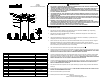
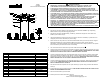
Table Of Contents

FIXTURE INSTALLATION
1. Feed the wire through the STEMS (1) and twist tightly onto the FIXTURE ASSEMBLY (2). Keep adding
additional stems until you desired hanging height is met.
2. Feed the wire through the CONNECTOR(4), CANOPY(3 ) and METAL PAD(10) then secure them to the
STEMS (1) use the HEX NUT(11).
3. Using the MOUNTING PLATE (5) mark holes on the ceiling for the WALL ANCHORS (13), drill holes on the
ceiling and push the WALL ANCHORS (13) into the ceiling.
4. Pull the wire out from the junction box, and install the MOUNTING PLATE (5) onto the junction box using the
MOUNTING SCREWS (6). Screw the WOOD SCREW(12) through the canopy hole into the WALL
ANCHOR(13) .This fixture is designed to be mounted on standard round or octagon junction box. The junction
box must be securely mounted to the structure of the building.
5. Trim off the excess wire to a minimum 6" beyond the STEM and strip each wire
5
8
".
6. Attach the Ground wire (Green) to the ground inside the outlet box (Generally green or bar copper wire) or the
GROUND SCREW (7) on the MOUNTING PLATE (5). NEVER CONNECT GROUND WIRE TO "HOT" WIRE!
FAILURE TO FOLLOW THIS COULD RESULT IN SERIOUS INJURY OR DEATH!
7. Connect the white fixture lead to the neutral (Generally white) wire in the outlet box. Fasten the wires together
with an approved fastener (WIRE NUT) (8). Starting 1" below the fastener, tightly wrap the connection with
electrical tape so that the connections seals the end of the fastener. MAKE SURE THERE ARE NO EXPOSED
WIRE OF STRANDS THAT COULD CAUSE A DANGEROUS SHORT CIRCUIT!
8. Connect the black fixture leads to the hot (Generally black) wire in the outlet box. Fasten the joined wires same
as previous step. NEVER REVERSE HOT AND NEUTRAL WIRES. FAILURE TO FOLLOW THIS COULD
RESULT IN SERIOUS INJURY OR DEATH!
9. Push the wires back into the junction box. Lift up the CANOPY (3) up to the ceiling, and secure with the END
NUTS (9).
10. Screw the BULB (14) into the sockets of the fixture.THIS FIXTURE IS RATED FOR 60 WATT LAMP. DO NOT
EXCEED THE RECOMMENDED WATTAGE!
11. Place the GLASS SHADE (15) to the bracket .
12. Restore power to the outlet at the breaker or fuse box.
1
6
5
8
3
9
7
2
4
ITEM DESCRIPTION
PART NUMBER
1
HVM STEM KIT (3"+6"+12"+18")X2 STM-H495803,06,12,18
2 FIXTURE ASSEMBLY FAS-H495905
3
CANOPY
CPY-H496905
4 CONNECTOR
CON-H496905
5
MOUNTING PLATE
MPT-H495905
6 MOUNTING SCREW HDW-H495905
7 GROUND SCREW
HDW-H495905
8 WIRE NUT HDW-H495905
9 END NUT HDW-H495905
10
METAL PAD
HDW-H495905
11
HEX NUT HDW-H495905
12 WOOD SCREW
HDW-H495905
13
WALL ANCHOR
HDW-H495905
14
BULB
NOT INCLUDED
15
GLASS SHADE GLS-H495301
IRENE
H495905
INSTALLATION INSTRUCTIONS
WARNING/CAUTION
· DISCONNECT POWER BEFORE RE-LAMPING OR WIRING THE FIXTURE. READ ALL INSTRUCTIONS
COMPLETELY BEFORE STARTING INSTALLATION.
· TO AVOID THE RISK OF FIRE OR SHOCK, FIXTURE MUST BE INSTALLED IN COMPLIANCE WITH ALL
APPLICABLE NATIONAL AND LOCAL ELECTRICAL/BUILDING CODES. THE INSTALLATION AND
MAINTENANCE OF THIS UNIT SHOULD BE COMPLETED BY A LICENSED ELECTRICIAN OR CERTIFIED
FACTORY TRAINED TECHNICIAN.
· CALIFORNIA PROP 65: THIS LIGHTING FIXTURE CONTAINS CHEMICALS KNOWN TO THE STATE OF
CALIFORNIA TO CAUSE CANCER, BIRTH DEFECTS, AND/OR OTHER REPRODUCTIVE HARM. WASH
HANDS AFTER USE.
· REMOVE THE FIXTURE, PARTS AND PARTS BAG(S) FROM THE CARTON. BEFORE DISCARDING THE
CARTON, DOUBLE CHECK TO MAKE CERTAIN THAT ALL PARTS ARE FOUND. INSPECT THE FIXTURE
PRIOR TO INSTALLATION FOR ANY DAMAGE TO THE FIXTURE.
· DIMMING: THE FIXTURE CAN BE CONTROLLED BY A WALL DIMMING DEVICE. ONLY USE
TRIAC/ELECTRONIC DIMMER. MAKE SURE THE CARTON IS MARKED FOR USE WITH LED COMPACT
FLUORESCENT-INCANDESCENT LIGHT SOURCE ONLY. THESE CAN BE PROVIDED BY YOUR LOCAL
ELECTRICAL DISTRIBUTOR, HOME CENTER, OR HARDWARE STORE.
· PLEASE CLEAN WITH A SOFT, DRY CLOTH ONLY! DO NOT USE CLEANSERS
www.hvlgroup.com
Questions? We're here to help!
Contact us at CustomerService@hvlgroup.com
15
14
10
11
13
12
HUDSON VALLEY LIGHTING