
Installation Sheet
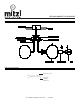
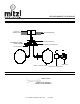
Table Of Contents
- ,H270603,
- GENERAL
- GENERAL
- INSTALLATION
- INSTALLATION
- STEP 1. Pull the wires out from the outlet box, and install mounting plate onto the outlet box using the (2) mounting screws. Strip the fixture wires ½” long at the ends.
- STEP 1. Pull the wires out from the outlet box, and install mounting plate onto the outlet box using the (2) mounting screws. Strip the fixture wires ½” long at the ends.
- STEP 2. Fasten bare ground wire to ground wire from the wall outlet box (usually green or copper color) or connect ground wire to green screw on the mounting plate.
- STEP 2. Fasten bare ground wire to ground wire from the wall outlet box (usually green or copper color) or connect ground wire to green screw on the mounting plate.
- STEP 3. Connect the neutral (white) fixture wire coming from the fixture base to neutral (usually white) outlet wire. Fasten both wires together with a plastic wire nut and tightly wrap the wire nut with electrical tape.
- STEP 3. Connect the neutral (white) fixture wire coming from the fixture base to neutral (usually white) outlet wire. Fasten both wires together with a plastic wire nut and tightly wrap the wire nut with electrical tape.
- STEP 4. Repeat the previous step with the hot (black wires). Make sure there are no exposed wires or strands that could cause a dangerous short circuit.
- STEP 4. Repeat the previous step with the hot (black wires). Make sure there are no exposed wires or strands that could cause a dangerous short circuit.
- FAILURE TO CONNECT THE APPROPRIATE WIRES CORRECTLY COULD RESULT IN SEROIUS INJURY OR DEATH!
- FAILURE TO CONNECT THE APPROPRIATE WIRES CORRECTLY COULD RESULT IN SEROIUS INJURY OR DEATH!
- FAILURE TO CONNECT THE APPROPRIATE WIRES CORRECTLY COULD RESULT IN SEROIUS INJURY OR DEATH!
- STEP 5. Carefully place connections back into the outlet box
- STEP 5. Carefully place connections back into the outlet box
- STEP 5. Carefully place connections back into the outlet box
- STEP 6. Lift Canopy up over the mounting plate and secure with set screws.
- STEP 6. Lift Canopy up over the mounting plate and secure with set screws.
- STEP 6. Lift Canopy up over the mounting plate and secure with set screws.
- STEP 7. Put the glass onto the glass fitter then secure it with the socket ring.
- STEP 7. Put the glass onto the glass fitter then secure it with the socket ring.
- STEP 7. Put the glass onto the glass fitter then secure it with the socket ring.
- STEP 8. Install the lamp(s). The fixture is rated for 60 watt type G lamp.
- STEP 8. Install the lamp(s). The fixture is rated for 60 watt type G lamp.
- STEP 8. Install the lamp(s). The fixture is rated for 60 watt type G lamp.
- DO NOT EXCEED RECOMMENDED WATTAGE!
- DO NOT EXCEED RECOMMENDED WATTAGE!
- DO NOT EXCEED RECOMMENDED WATTAGE!
- STEP 9. Restore power to the circuit at breaker or fusebox
- STEP 9. Restore power to the circuit at breaker or fusebox
- STEP 9. Restore power to the circuit at breaker or fusebox
- DIMMING
- DIMMING
- CLEANING
- CLEANING
- ASSEMBLY AND MOUNTING DIAGRAM
- ASSEMBLY AND MOUNTING DIAGRAM
- WIRE NUT/TAPING DIAGRAM
- WIRE NUT/TAPING DIAGRAM
- H270 603 M48
- GENERALITÉ
- GENERALITÉ
- INSTALLATION
- INSTALLATION
- PAS 3. Relier le fil neutre (blanc) venant de la base du dispositif au fil neutre (généralement blanc) de la boîte de dérivation. Relier les deux fils entre eux à l’aide d’un serre-câble en plastique et envelopper le serre-câble de ruban isolant bien ...
- PAS 3. Relier le fil neutre (blanc) venant de la base du dispositif au fil neutre (généralement blanc) de la boîte de dérivation. Relier les deux fils entre eux à l’aide d’un serre-câble en plastique et envelopper le serre-câble de ruban isolant bien ...
- RÈGLAGE D’INTENSITÉ
- RÈGLAGE D’INTENSITÉ
- NETTOYAGE
- NETTOYAGE
- SCHÉMA D’ASSEMBLAGE ET DE MONTAGE
- SCHÉMA D’ASSEMBLAGE ET DE MONTAGE
- SCHÉMA DE BORNE DE RACCORDEMENT ET D’ENVELOPPAGE AVEC RUBAN ISOLANT
- SCHÉMA DE BORNE DE RACCORDEMENT ET D’ENVELOPPAGE AVEC RUBAN ISOLANT

H270603 MARGOT
FLUSH MOUNT
www.hudsonvalleylighting.com/mitzi | #mymitzi
SCHÉMA D’ASSEMBLAGE ET DE MONTAGE
SCHÉMA DE BORNE DE RACCORDEMENT ET D’ENVELOPPAGE AVEC RUBAN ISOLANT
BAGUE POUR DOUILLE
VIS DE MISE À TERRE
VIS DE FIXATION
AMPOULE
BOÎTE DE
DÉRIVATION
CACHE-PITON
PLAFOND/PAROI
PLAQUE DE MONTAGE
VIS DE MONTAGE
RUBAN ISOLANT
CONNECTEUR APPROUVÉ
(BORNE DE RACCORDEMENT)
ABAT-JOUR DE VERRE