
Installation Sheet
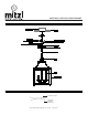
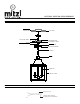
Table Of Contents
- ,H259704L,H259704S,
- GENERAL
- INSTALLATION
- STEP 1. Pull the wires out from the outlet box, and install mounting plate onto the outlet box using the (2) mounting screws. Strip the fixture wires ½” long at the ends.
- STEP 2. Choose the length of the chain you need, then weave the fixture wire and the fixture grounding wire through the chain. Then connect one end of the chain with the loop.
- STEP 3. Secure the screw collar loop to nipple.
- STEP 4. Thread the fixture wire and fixture grounding wire through the loop ring, canopy, screw collar loop, nipple and mounting plate.
- STEP 5. Connect the other end of the chain with screw collar loop. Trim off excess wire to min 6” beyond the canopy. Strip each wire end 1/2”.
- STEP 6. Fasten bare ground wire to ground wire from the wall outlet box (usually green or copper color) or connect ground wire to green screw on the mounting plate.
- STEP 7. Connect the neutral (white) fixture wire coming from the fixture base to neutral (usually white) outlet wire. Fasten both wires together with a plastic wire nut and tightly wrap the wire nut with electrical tape.
- STEP 8. Repeat the previous step with the hot (black wires). Make sure there are no exposed wires or strands that could cause a dangerous short circuit.
- FAILURE TO CONNECT THE APPROPRIATE WIRES CORRECTLY COULD RESULT IN SEROIUS INJURY OR DEATH!
- STEP 9. Carefully place connections back into the outlet box.
- STEP 10. Mount the canopy to the mounting plate by inserting the screw collar loop, then secure with loop ring.
- STEP 11. Install the lamps. The fixture is rated for 60 watt type B lamp. DO NOT EXCEED RECOMMENDED WATTAGE!
- STEP 12. Restore power to the circuit at breaker or fuse box.
- DIMMING
- CLEANING
- ASSEMBLY AND MOUNTING DIAGRAM
- WIRE NUT/TAPING DIAGRAM
- ,H259704 B45
- GENERALITÉ
- INSTALLATION
- PAS 4. Faire passer le fil du dispositif et le fil de mise à terre par la bague de serrage, le cache-piton, l’anneau à visser, le téton et la plaque de montage.
- PAS 5. Relier l’autre bout de la chaîne avec l’anneau à visser. Couper l’excédent de fil jusqu’à un minimum de 15,3 cm (6”) au-delà du cache-piton. Dénuder chaque extrémité des fils jusqu’à 1,3cm (½”).
- RÈGLAGE D’INTENSITÉ
- NETTOYAGE
- SCHÉMA D’ASSEMBLAGE ET DE MONTAGE
- SCHÉMA DE BORNE DE RACCORDEMENT ET D’ENVELOPPAGE AVEC RUBAN ISOLANT

H259704S, H259704L LEIGH PENDANT
www.hudsonvalleylighting.com/mitzi | #mymitzi
SCHÉMA D’ASSEMBLAGE ET DE MONTAGE
SCHÉMA DE BORNE DE RACCORDEMENT ET D’ENVELOPPAGE AVEC RUBAN ISOLANT
RUBAN ISOLANT
CONNECTEUR APPROVÉ
(BORNE DE RACCORDEMENT)
CACHE-PITON
TÉTON
AMPOULE
BOÎTE DE
DÉRIVATION
PLAFOND
ANNEAU À VISSER
VIS DE MONTAGE
VIS DE MISE À TERRE
PLAQUE DE MONTAGE
BAGUE DE SERRAGE
CHAÎNE
ANNEAU
NOUAGE DE CÂBLES
CORPS DU CADRE