
Installation Sheet

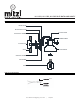

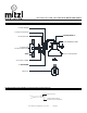
Table Of Contents
- ,H111301,H111302,H111303,
- GENERAL
- INSTALLATION
- STEP 1. Pull the wires out from the outlet box, and install mounting plate onto the outlet box using the (2) mounting screws. Strip the fixture wire ends 5/8”
- STEP 2. Fasten bare ground wire to ground wire from the wall outlet box (usually green or copper color) or connect ground wire to green screw on the mounting plate.
- STEP 3. Connect the neutral (white) fixture wire coming from the fixture base to neutral (usually white) outlet wire. Fasten both wires together with a plastic wire nut and tightly wrap the wire nut with electrical tape.
- STEP 4. Repeat the previous step with the hot (black wires). Make sure there are no exposed wires or strands that could cause a dangerous short circuit.
- FAILURE TO CONNECT THE APPROPRIATE WIRES CORRECTLY COULD RESULT IN SEROIUS INJURY OR DEATH!
- STEP 5. Carefully place connections back into the outlet box
- STEP 6. Place Back plate over the mounting plate and secure with Set Screws
- STEP 7. Lift Glass into position and screw thumb screws into glass fitter.
- STEP 8. Install the lamp(s). The fixture is rated for 60 watt type G lamp.
- DO NOT EXCEED RECOMMENDED WATTAGE!
- STEP 9. Restore power to the circuit at breaker or fusebox.
- DIMMING
- CLEANING
- ASSEMBLY AND MOUNTING DIAGRAM
- WIRE NUT/TAPING DIAGRAM
- ,H111301,H111302,H111303 M37,
- GENERALITÉ
- INSTALLATION
- PAS 3. Relier le fil neutre (blanc) venant de la base du dispositif au fil neutre (généralement blanc) de la boîte de dérivation. Relier les deux fils entre eux à l’aide d’un serre-câble en plastique et envelopper le serre-câble de ruban isolant bien ...
- RÈGLAGE D’INTENSITÉ
- NETTOYAGE
- SCHÉMA D’ASSEMBLAGE ET DE MONTAGE
- SCHÉMA DE BORNE DE RACCORDEMENT ET D’ENVELOPPAGE AVEC RUBAN ISOLANT

H111301, H111302, H111
303 RILEY BATH AND VANITY
www.hudsonvalleylighting.com/mitzi | #mymitzi
SCHÉMA D’ASSEMBLAGE ET DE MONTAGE
OUTLET BOX
WALL
GRO UN D SCREW
MOUNTING SCREW
MOUNTING PLATE
SET SCREW
BACK PLATE
LAMP
THUMB SCREW
GLASS SHADE
GLASS FITTER
SCHÉMA DE BORNE DE RACCORDEMENT ET D’ENVELOPPAGE AVEC RUBAN ISOLANT
RUBAN ISOLANT
CONNECTEUR APPROVÉ
(BORNE DE RACCORDEMENT)
PLAQUE ARRIÈRE
PLAQUE DE MONTAGE
VIS DE MONTAGE
BOÎTE DE DÉRIVATION
PAROI
VIS DE MISE À TERRE
VIS DE FIXATION
AMPOULE
ABAT-JOUR EN VERRE
VIS À SERRAGE À MAIN
SUPPORT DE VERRE