
Installation Sheet
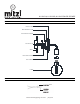
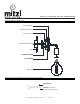
Table Of Contents
- ,H110101A,H110101B,H110102,
- GENERAL
- INSTALLATION
- STEP 1. Pull the wires out from the outlet box, and install mounting plate onto the outlet box using the (2) mounting screws. Strip the fixture wire ends 5/8”
- STEP 2. Fasten bare ground wire to ground wire from the wall outlet box (usually green or copper color) or connect ground wire to green screw on the mounting plate.
- STEP 3. Connect the neutral (white) fixture wire coming from the fixture base to neutral (usually white) outlet wire. Fasten both wires together with a plastic wire nut and tightly wrap the wire nut with electrical tape.
- STEP 4. Repeat the previous step with the hot (black wires). Make sure there are no exposed wires or strands that could cause a dangerous short circuit.
- FAILURE TO CONNECT THE APPROPRIATE WIRES CORRECTLY COULD RESULT IN SEROIUS INJURY OR DEATH!
- STEP 5. Carefully place connections back into the outlet box
- STEP 6. Place Back plate over the mounting plate and secure with Set Screws
- STEP 7. Install the lamp(s). The fixture is rated for 60 watt type G lamp.
- DO NOT EXCEED RECOMMENDED WATTAGE!
- STEP 8. Restore power to the circuit at breaker or fusebox.
- DIMMING
- CLEANING
- ASSEMBLY AND MOUNTING DIAGRAM
- WIRE NUT/TAPING DIAGRAM
- ,H110101A,H110101B,H110102M36
- GÉNÉRALITÉ
- INSTALLATION
- STEP 1. Pull the wires out from the outlet box, and install mounting plate onto the outlet box using the (2) mounting screws. Strip the fixture wire ends 5/8”
- STEP 2. Fasten bare ground wire to ground wire from the wall outlet box (usually green or copper color) or connect ground wire to green screw on the mounting plate.
- STEP 3. Connect the neutral (white) fixture wire coming from the fixture base to neutral (usually white) outlet wire. Fasten both wires together with a plastic wire nut and tightly wrap the wire nut with electrical tape.
- STEP 4. Repeat the previous step with the hot (black wires). Make sure there are no exposed wires or strands that could cause a dangerous short circuit.
- FAILURE TO CONNECT THE APPROPRIATE WIRES CORRECTLY COULD RESULT IN SEROIUS INJURY OR DEATH!
- STEP 5. Carefully place connections back into the outlet box
- STEP 6. Place Back plate over the mounting plate and secure with Set Screws
- STEP 7. Install the lamp(s). The fixture is rated for 60 watt type G lamp.
- DO NOT EXCEED RECOMMENDED WATTAGE!
- STEP 8. Restore power to the circuit at breaker or fusebox.
- RÈGLAGE D’INTENSITÉ
- NETTOYAGE
- SCHÉMA D’ASSEMBLAGE ET DE MONTAGE
- SCHÉMA DE BORNE DE RACCORDEMENT ET D’ENVELOPPAGE AVEC RUBAN ISOLANT

H110101A, H110101B, H110102 CHLOE
SCONCE
www.hudsonvalleylighting.com/mitzi | #mymitzi
SCHÉMA D’ASSEMBLAGE ET DE MONTAGE
OUTLET BO X
WALL
GRO UN D SCREW
MOUNTING SCREW
MOUNTING PLATE
SET SCREW
BACK PLATE
LAMP
SCHÉMA DE BORNE DE RACCORDEMENT ET D’ENVELOPPAGE AVEC RUBAN ISOLANT
ELECTRICAL
TAPE
APPROVED
FASTNER
(WIRE NUT)
PAROI
BOÎTE DE DÉRIVATION
VIS DE MONTAGE
PLAQUE DE MONTAGE
PLAQUE ARRIÈRE
VIS DE FIXATION
VIS DE MISE À TERRE
AMPOULE
CONNECTEUR APPROVÉ
(BORNE DE RACCORDEMENT)
RUBAN ISOLANT