
User guide
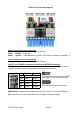

1.2 M3-ATX Connection diagram
Power Input Connectors (right side)
Red Battery + (positeive, un-switched battery)
Black Battery - (negative)
White Ignition (switched battery, positive. Can test by connecting it to Battery +)
Power Output Connectors (left side)
Hard drive wire harness (HDD, SATA-HDD, Floppy)
ON/OFF and THUMP wire harness (connects to M3-ATX pin header)
-ON/OFF wire harness (red/back) to connect to motherboard’s ON/OFF pin headers.
-THUMP (white) to connect to amplifier remote ON/OFF connector.
Wire harness for motherboard ON/OFF
switch and Thump control (optional)
Wire harness for serial connection.
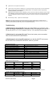
IMPORTANT: Always use the “Hibernate” feature on your PC, never use “Standby”.
P0: In this mode, the M3-ATX behaves like a regular ATX power supply.
M3-ATX User Guide Page 2
P Off-delay Hard-off
P0
Standard PSU mode
P1
5sec 1 min
P2
1 min 5 min
P3
30 min 2 hour
P4
custom custom