No.99MBH001B1 SERIES No.
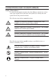
CONVENTIONS USED IN USER'S MANUAL Safety Precautions To operate the instrument correctly and safely, Mitutoyo manuals use various safety signs (Signal Words and Safety Alert Symbols) to identify and warn against hazards and potential accidents. The following signs indicate general warnings: Indicates an imminently hazardous situation which, if not avoided, will result in serious injury or death.
1 INTRODUCTION CONVENTIONS USED IN USER'S MANUAL On Various Types of Notes The following types of notes are provided to help the operator obtain reliable measurement data through correct instrument operation. IMPORTANT NOTE TIP • An important note is a type of note that provides information essential to the completion of a task. You cannot disregard this note to complete the task.
WARRANTY In the event that the Mitutoyo Digi-Derm should prove defective in workmanship or material, within one year from the date of original purchase for use, it will be repaired or replaced, at our option, free of charge upon its prepaid return to us.
1 INTRODUCTION CONTENTS CONVENTIONS USED IN USER'S MANUAL ......................... i WARRANTY ........................................................................... iii 1 INTRODUCTION .............................................................. 1-1 1.1 Preface ................................................................................. 1-1 1.2 Application ............................................................................ 1-1 1.3 Nomenclature and Function .............................
v
1 INTRODUCTION 1 INTRODUCTION 1.1 Preface The Mitutoyo Digi-Derm is a coating thickness gage of non-destructive type with a digital display. If it is connected to the Digimatic Miniprocessor, measurements can be printed and processed. Read this operation manual carefully before use. 1.2 Application 1) No.179-741, 179-745 & 179-746 Capable of measuring the thickness of the following types of nonmagnetic plating, films, etc. applied to magnetic materials (Iron, Nickel, Cobalt, etc.
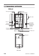
1.3 Nomenclature and Function 1) Main unit Zero adj. volume Display Gain adj. volume Probe cable Power sw. Data output connector or Analog output connector (179-741) Inch/mm conversion sw. Hold key Print key (except for 179-741) AC adaptor jack Battery lid Rod stand (Rear view) 1-2 MANUAL No.
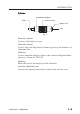
1 INTRODUCTION 2) Probe Stopper Cable Knurled sleeve Bobbin case Core Fig. 1 Zero adj. volume Used to set the display to zero. Gain adj. volume Used to adjust the Digi-Derm to indicate precisely the thickness of calibration film. Print key Used to output the displayed value to the connected Digimatic Miniprocessor. (except for 179-741) Hold key Holds and releases the displayed value alternately. Inch/mm conversion sw. Converts the displayed mm values to inch values and vice versa. MANUAL No.
1-4 MANUAL No.
2 OPERATION 2 OPERATION 2.1 Setting Power Source The Digi-Derm operates from either dry batteries or AC power source. Perform the following setup with the Digi-Derm turned OFF OFF. 1) Dry Batteries Use four pieces of R6 (SUM-3). First, remove the battery lid on the bottom of the case by pushing it in the arrow-marked direction, then set the batteries over the ribbon in the proper polarity (+/-). Pulling the ribbon removes the batteries. Ribbon Fig.
2.2 Calibration Be sure to perform calibration before measurement. Calibration includes two adjustment: zero adjustment and gain adjustment. The following is a calibration procedure using the provided reference specimen as the base metal. 2.2.1 Zero adjustment (1) Turn the Zero and Gain adj. volume to the approximate center of each range. (2) While setting the probe to the specimen surface, turn the Zero adj. volume until the display becomes zero.
2 OPERATION 2.2.2 Gain adjustment Perform gain adjustment after zero adjustment. (1) Place the provided calibration film on the reference specimen. For accurate measurement, use a calibration film of thickness as close to that of the coating to be measured as possible. (2) Applying the probe on the calibration film, turn the Gain adj. volume until the Digi-Derm indicates exactly the thickness as designated on the film. Refer to 2.2.1 (2) for the way the probe is applied.
2.2.3 Notes on calibration Although the provided reference specimen was used as a base metal in the above example to explain calibration procedures, use a base metal identical in material, shape, and thickness with that of the workpiece for calibration, for improved accuracy in measurement. If such a base metal is not available, use one as similar in these three characteristics as possible to the workpiece to be actually measured.
2 OPERATION 2.3 Measurement 2.3.1 Measurement method If calibration is complete, the Digi-Derm is ready for measurement. It will indicate the coating thickness on the point where the probe is applied. For accurate measurement, the probe should be applied to the same point as that where calibration was performed. Calibration the Digi-Derm regularly at appropriate intervals. 1) Measurement on a curved or round surface The V-grooves of a probe allow exact measurement on a curved or round surface.
2.3.2 Holding displayed value Pressing the Hold key with the probe applied on the measured surface H " or "← ← " (179-741) sigh indication. The holds the display with "H analog output is not held in the HOLD state (179-741). To release the Digi-Derm from HOLD state, press the key again. 2.3.3 Outputting displayed value If data print-out and processing are needed, connect the Data output connector on the Digi-Derm to the Digimatic Mini-processor* (optional) with the cable No. 936937 (optional).
3 SPECIFICATION AND SAFE-KEEPING 3 SPECIFICATION AND SAFE-KEEPING 3.1 Specifications 3.1.1 General specifications Code No. 179-741 Workpiece Range 179-745 179-746 179-755 179-756 Non-magnetic coating on magnetic material Non-conductive coating on on non-magnetic material 1.500mm (.05900") 1.000mm (.03930") Resolution 0.001mm/.00005" Accuracy (range) ±3µm±1 digit (0-0.1mm) ±3%±1 digit (0.1-1.1mm) ±4%±1 digit (1.1-1.5mm) Display 3.
Code No. 179-741, 179-745, 179-746 Standard accessories 179-755, 179-756 • SUM-3 .................................... 4 • Carrying case ......................... 1 • Case for films ......................... 1 • Base metal, SPC (No. 933038) ...... 1 • Calibration film set (No. 945014) 1 25µm (No.527599) 50µm (No.527600) 100µm (No.527601) 250µm (No.527602) 500µm (No.527603) 1000µm (No.527604) 1500µm (No.685013) ....... 1ea. Optional accessories • AC adaptor No.528041 No.528041A No.528041D No.528041E No.
3 SPECIFICATION AND SAFE-KEEPING 2) Data format d1 d2 d3 d4 d5 d6 d7 d8 d9 MSD All "F" (1111) Ordinary measurement "F" (1111) d10 d11 d12 d13 LSD Sign +: 0 (0000) -: 8 (0001) Measurement decimal point 3 (1100) Unit mm: 0 (0000) inch: 1 (1000) Fig. 9 Data consists of 13 digits (d1 thru d13); each digit consists of 4 bits. Data output to a linked data processor or other peripheral is effected via pin No.2 from d1 to d13 in bit serial, from the LSB (20) to the MSB (23) for each digit.
3.2 Safe-keeping For long service life of Digi-Derm, observe the following maintenance points: • Keep the Digi-Derm clean and avoid moisture in the storage location. • Do not apply excessive force or shocks to the Digi-Derm. • Turn the Digi-Derm OFF after use. • Remove the batteries from the Digi-Derm when the Digi-Derm is to be left unused for a long period. • Avoid rubbing or excessive pressing of the measuring face of the probe to prevent scratches or deformation.
3 SPECIFICATION AND SAFE-KEEPING MANUAL No.