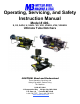
Operating, Servicing, and Safety Instruction Manual Model # 400- S, S2, SADJ, U, UADJ / VS, VS2, VSADJ, VSU, VSUADJ Ultimate Tube Notchers CAUTION: Read and Understand These Operating, Servicing, and Safety Instructions, Before Using This Machine. 1-800-467-2464 10 Cooperative Way Wright City, MO 63390 P.O. Box 110 Foristell, MO 63348 1-636-745-7757 Fax 1-636-745-2874 www.mittlerbros.
-2- Table of Contents • Crate Contents Pg.3 • Safety Pg.4 • Machine Set Up Pg.5 • Operation Pg.6 • Two Sided Notch Operation Pg.9 • General Maintenance Pg.10 • Gib Adjustments Pg.10 -12 • Two Sided In/Out Gib Adjustment Pg.12-13 • Gib Replacement Pg.14-15 • Hand wheel Shaft Replacement Pg.16-17 • 400 Single Speed to Variable Speed Conversion Pg. 18-22 • Troubleshooting Pg.23 • Optional Part Installation Pg. 24-26 • Cutter Part Numbers Pg.27 • Technical Diagrams and NotesPg.
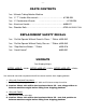
-3- CRATE CONTENTS 1ea. Ultimate Tubing Notcher Machine 1ea. ¼” “T” Handle Allen wrench…………………………………#1100-504 1ea. ¾” Combination Wrench …………………………………….#1100-504 2ea. Aluminum Handle…………………………………………….#400-021 2ea. Shoulder Bolts………………………………………………..#750-SHLDRBOLT.5X3 REPLACEMENT SAFETY DECALS 1ea. “Do Not Operate Without Guard In Place…” Sticker #400-542 1ea. “Do Not Operate Without Safety Glasses…” Sticker #400-543 1ea. “Stop Machine Before…” Sticker #400-518 1ea.
-4- SPECIFICATIONS MODEL #400-S: Max Diameter = 2” OD Standard Vise, 2 3/8” OD Upgraded Vise 1 HP AC Motor, 115 Volts / 15 Amp, 1 Phase 60 Hertz MODEL #400-VS: Max Diameter = 2” OD Standard Vise, 2 3/8” OD Upgraded Vise 1-1/2 HP AC Motor, 115, 208, 230, 240 Volts / 15 Amp, 1 Phase 50/60 Hertz MODEL #400-VS2: Max Diameter = 2” OD Standard Vise, 2 1/2” OD Upgraded Vise 1-1/2 HP AC Motor, 115, 208, 230 Volts / 15 Amp, 1 Phase 50/60 Hertz POWER SOURCE: Electric
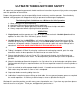
-5- ULTIMATE TUBING NOTCHER SAFETY All supervisory and operating personnel should read these instructions to prevent injury and assure proper and safe operation of the machine. Proper safety precautions are the responsibility of each and every machine operator. Conscientiously followed safety programs will help prevent injury to personnel and damage to equipment. The following Basic Guidelines are a Minimum for Safe Operation 1. 2. 3. 4. Wear safety glasses when operating.
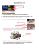
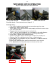
-6- MACHINE SET UP #2 1/2” #1 UnboltAllen from Bolt shipping crate. from Bottom of Stand 1. Remove cardboard box and upper wood frame work from shipping crate. 2. Unbolt the Ultimate Tubing Notcher from the crate base by removing the four (4) bolts. 3. Remove the protective plastic film from the chip shield. 4. Install the Crank Handle Knobs using the supplied shoulder bolts. #4 Shoulder Bolts #4 Crank Handle Knobs 5.
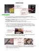
-7- OPERATION #1, Standard Machine ON / OFF Switch #1, Variable Speed Machine Run/Stop Switch #1, Variable Speed Machine MASTER Switch WEAR SAFETY GLASSES 1. Be sure your machine is turned off and is plugged into the proper power source. [Both the Single Speed & Variable Speed machine operate on 110 Volt single (1) phase electric. Switch is on the left side of the main base plate for single speed and on the control box as shown above.
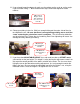
-85. If you already know the degree of notch, use the pointer on the scale to set the angle. If you used the sliding “T” bevel method from step 3 record the degree for future notches. #5, Pointer & Degree Scale. This example is set to 75° or 15° from 90° 6. Clamp your tubing in the vise. Stick just enough tubing out the cutter side of the vise to complete the cut. Be sure that there is enough tubing sticking out to avoid the cutter contacting the vise before notch is complete.
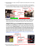
-98. After setting your vise angle, jaw height and tightening everything down you are ready to make a notch. 9. The main feed direction for notches is In & Out. The Left to Right is used to position the tube in the best location on the cutter. All cutting is done on the length (side) of the cutter and not the end. Keep the tubing as close to the spindle as possible.
- 10 - TWO SIDED NOTCH OPERATION Requires Model #400-S2 or Model #400-VS2 Front Side Notch Cluster Joint Back Side Notch Front Side Notch – Follow Instructions on Pages 5 – 7. Back Side Notch 1. Turn In/Out Handwheel counterclockwise to move tube away from cutter. 2. Adjust cutter speed to slowest speed. NOTE: Allows cutter holding setscrews to be properly positioned to remove cutter. 3. Turn OFF Cutter switch. 4.
- 11 - GENERAL MAINTANANCE SAFETY FIRST / BE SURE MACHINE IS UNPLUGGED BEFORE ANY MAINTAINCE IS PERFORMED 1. Lubrication is required at the grease fittings on the feed table 3 times per year. Use any general purpose grease as required for smooth operation. 2. Keep as clean as possible at all times for long life. Be sure the Cooling slots for the motor fan are kept clean as well as the cooling louvers on the Variable speed control box. 3.
- 12 5. Once you are satisfied with the adjustments tighten the five gib mounting bolts and recheck your adjustments. This procedure may take a few tries. You can now remount the vise to the mounting plate. 6. You will need to realign the vise to be square with the cutter. Insert a piece of 1-1/4” OD tubing or shaft into the spindle and lightly tighten the set screws. Hold a combination square or machinist square tight in the groove of the V jaw as shown.
- 13 5. Turn clockwise each Gib adjusting screw, on the back side of the vise mounting plate, this will “spread & tighten” the gibs. Make very small adjustments at a time! After making an adjustment turn the hand wheel and run through the entire range of travel feeling for smooth and snug movement. If it seems too tight, back the adjusting screws off a very small amount and then use a soft head hammer and tap the gib opposite the adjusting screws and repeat the process.
- 14 3. Turn In/Out Handwheel counterclockwise to move vise assembly to front side (Left side). 4. Install #1 Center Gib Adjustment Screw. NOTE: Center Adjustment Screws MUST be removed for proper operation to move vise assembly through entire travel. 5. Turn clockwise each Front Side Gib Adjusting Screw (qty. 2) to move the opposite side gib. This will “spread & tighten” the gibs.
- 15 - GIB REPLACEMENT 1. Mount right side lower steel gib with 5/16” x 18 x 1” long socket head screws (steel gib with holes drilled on bottom, plus 2 holes on side). NOTE: Cap screws enter from under base plate. 2. Insert 2 steel dowel pins into right lower gib and drive pins into gib and base plate. 3. Tighten 5/16” x 18 x 1” socket head screws on right lower gib. 4. Install Left side lower steel gib with 5/16” x 18 x 1” long socket head screws – DO NOT TIGHTEN. 5.
- 16 16. Once you are satisfied with the adjustments tighten the five gib mounting bolts and recheck your adjustments. This procedure may take a few tries. You can now remount the vise to the mounting plate. 17. You will need to realign the vise to be square with the cutter. Insert a piece of 1-1/4” OD tubing or shaft into the spindle and lightly tighten the set screws. Hold a combination square or machinist square tight in the groove of the V jaw as shown.
- 17 - HAND WHEEL SHAFT REPLACEMENT 1. Remove bolts holding vise base to compound feed table – remove vise. (see page 9 steps 1 & 2) Upper Adjustment Screw Replacement – Left-to-Right Movement: 2. Remove upper slider block adjustment screws using 3/16” Allen wrench – located on backside of upper slide gib assembly. 3. Loosen (Do Not Remove) 5 gib mounting 5/16” socket head cap screws on vise mounting plate to allow front gib clearance. 4.
- 18 23. Remove snap ring on each side of lower bronze nut. 24. Remove bronze nut from housing and discard. 25. Install new bronze nut (left hand thread) in lower mounting block. 26. Install new snap ring on each side of bronze nut. 27. Use 1/8” drill bit and drill point the bronze nut through the set screw hole in mounting block – Do Not drill through bronze bushing. 28. Install/Tighten set screw – use 1/8” Allen wrench. 29. Remove Nylok nut from lower hand wheel – use ¾” socket. 30.
- 19 - 400 Single Speed to Variable Speed Conversion #400-202 See kit contents on page 22 1. Unpack the boxes and be sure all the parts are included. See the list at the end of these instructions. 2. Unplug the machine from any power source. Remove the switch box from the base plate by removing the cover and unscrewing from the base plate. Remove Cover Unscrew from Base Plate 3. Remove the Love Joy Cover by removing the two screws. Then loosen the set screws on each half of the Love Joy coupling.
- 20 Motor Side Spindle Side Drill & Tap 1” deep for 5/16”-18 7. Slide the large bore (1”) Love Joy coupler half onto the spindle. Be sure the “fingers” are pointing toward the motor location and that the key is installed in the key way. Do not tighten down set screw at this time. Spider Spindle Side Large Bore Gearbox Side Small Bore Side Fingers Small 3/4” Bore Large 1” Bore 8. Assemble the motor to the gear box.
- 21 10. Set the motor / gearbox assembly onto the mounting plate. While someone is holding the motor end up install the mounting bolts finger tight. Use mounting holes farthest from the spindle as shown below. New Mounting Holes Spindle (Love Joy coupler removed) Old Mounting Holes 11. Slip the two Love Joy coupler halves together with your fingers, being sure the spider is still locked in the “fingers”. Tighten the set screws and snug up the motor / gearbox mounting bolts. Set Screw Set Screw 12.
- 22 Conduit Nut Conduit Elbow Elbow Goes Here 16. Wire the control box to the motor as shown by the included wiring diagram. Use the supplied wire nuts and then use electrical tape for added safety. 17. Wire the input cord correctly for the style and voltage you are using, refer to enclosed wiring diagram. 18. Check all bolts for tightness and all electrical connections. Once you are sure everything is tight and correct set the master switch to OFF and the run switch to STOP.
- 23 - Variable Speed Conversion Kit Wiring Diagram
- 24 - TROUBLESHOOTING PROBLEM: CAUSE / SOLUTION: Machine does not turn on. 1. 2. 3. 4. Check plug & power cord. Check circuit breaker and panel. Check machine switch / switches. Check fuses in speed control box. (VS only) Machine stops working. 1. 2. 3. 4. 5. Machine overload or power cord. Check plug & power cord. Check circuit breaker and panel. Check machine switch / switches. Check fuses in speed control box. (VS only) “HOOKING” .Top of tube gets caught by cutter & bent down. 1. 2. 3. 4. 5.
- 25 - Optional Ultimate Tube Notcher Accessories 400-100 Chip Tray Installation Instructions Kit Contents: 1ea. 2ea. 2ea. 1ea. Tray 3/8-16 x 2” SHCS Nuts Instruction Sheet 1. Loosen and remove one of the Spindle Bearing Block mounting bolts as shown. Be sure to remove only one bolt. Remove one bolt 2. Replace the removed bolt with one of the supplied 2” long SHCS as shown below. Tighten the bolt. Replace with 2” SHCS 3. Repeat steps 1 & 2 above for the remaining bolt. 4.
- 26 - 400-A400 Ultimate Roller Stand Assembly Instructions Kit Contents: 16ea. 5/16-18x1/2 HHCS 2ea. 3/8-16x4 HHCS, 2ea. 3/8-16x1-3/4 HHCS 4ea. 3/8 Flat Washers 4ea. 3/8 Lock Washers 4ea. 3/8-16 Nuts 2ea. Swivel Casters, Locking 2ea. Solid Casters 1ea. Instruction Sheet 1. Uncrate the stand. Tip the stand up onto its end by lifting the round tube handle. Swivel Casters This end Solid Casters This end 2.
- 27 - 4. Set the Ultimate notcher onto the stand using a hoist and a pair of slings as outlined below. The On / Off switch and / or control panel should be on the same side of the stand as the cutter holder holes on the middle shelf. BE EXTREMLY CAREFULL WHEN MOVING THE NOTCHER ASSEMBLY, UNIT WEIGHS ALMOST 400 LBS. Using A Hoist 5. Once the notcher is setting on the stand line up the mounting holes in the machine base plate with the holes in the stand.
- 28 - CUTTER PART NUMBERS Tube OD Part# Pipe Size Cut Length Bushing # 2-3/8” 400-525 2” 4” 2” 400-526 1.90” 400-527 1-3/4” 400-528 1.
- 29 - Optional Vise Accessories Vise Jaw Shim 1100-100 Vise Jaw Shim required for 1/2” & 5/8” OD Tubing Adjustable Height Vise Kits Example Notch Make Accurate Offset Notches Add to your existing vise to make it height adjustable 1100-ASU 1100-AUU Jaw Kit for Standard Vise Jaw Kit for Upgraded Vise Vise Stop Assembly 400- 401 Vise Stop Assembly
- 30 - MACHINE EXPLODED VIEW N:\Product\Product Documentation\400 Ultimate\Manual\400 Owners Manual VER 5 09-03-2010.
- 31 - In & Out Repair Kit N:\Product\Product Documentation\400 Ultimate\Manual\400 Owners Manual VER 5 09-03-2010.
- 32 - Left & Right Repair Kit N:\Product\Product Documentation\400 Ultimate\Manual\400 Owners Manual VER 5 09-03-2010.
- 33 - L-Gib Assembly N:\Product\Product Documentation\400 Ultimate\Manual\400 Owners Manual VER 5 09-03-2010.
- 34 - Base Assembly N:\Product\Product Documentation\400 Ultimate\Manual\400 Owners Manual VER 5 09-03-2010.
- 35- Spindle Assembly N:\Product\Product Documentation\400 Ultimate\Manual\400 Owners Manual VER 5 09-03-2010.
- 36 - Vise Base Assembly N:\Product\Product Documentation\400 Ultimate\Manual\400 Owners Manual VER 5 09-03-2010.
- 37 - Vise Assemblies N:\Product\Product Documentation\400 Ultimate\Manual\400 Owners Manual VER 5 09-03-2010.
- 38 - CAUTION: Read and Understand These Operating, Servicing, and Safety Instructions, Before Using This Machine. 1-800-467-2464 10 Cooperative Way Wright City, MO 63390 P.O. Box 110 Foristell, MO 63348 1-636-745-7757 Fax 1-636-745-2874 www.mittlerbros.