-1- Operating, Servicing, and Safety Manual Model # 2500 180° Hydraulic Bender CAUTION: Read and Understand These Operating, Servicing, and Safety Instructions, Before Using This Machine. 1-800-467-2464 10 Cooperative Way Wright City, MO 63390 P.O. Box 110 Foristell, MO 63348 1-636-745-7757 Fax 1-636-745-2874 www.mittlerbros.
-2- Table of Contents • Safety Pg.3 • Hydraulic Safety Precautions Pg.4 • Prep/ Set Up Pg.4 • Bender Contents Pg.5 • Uncrate and Set Up Pg.6 • Hydraulic System Pg.7 • Getting Ready To Bend Pg.8-9 • Digital Readout Operation Pg.9 • Tubing Spring Back Pg.9 • Mathematics For Hyd. Tube Bender Pg.10-13 • Technical Diagram Pg.14-22 • Maintenance Pg.23-24 • Optional Equipment Pg.
-3- SAFETY The purpose of the safety section of this manual is to inform operators and maintenance personnel of the precautions to be taken while operating or servicing the machine. The following are a few basic guidelines to follow, but as with any type of machinery good judgment and a safe attitude should be applied at all times. 1 Always disconnect power, lock-out and tag-out machine per OSHA regulations before attempting to service this machine. 2.
-4- HYDRAULIC SAFETY PRECAUTIONS WARNING General Operation • All WARNING statements must be carefully observed to help prevent personal injury. • Before operating the pump, all hose connections must be tightened with the proper tools. Do not over tighten. Connections should only be tightened securely and leak-free. Over tightening can cause premature thread failure or high pressure fittings to split at pressures lower than their rated capacities.
-5- #2500 BENDER CONTENTS • 1ea Main bender assembly mounted to stand • 1ea Swivel work table • 1ea Rectangle shaped shelf • 1ea Angle shaped shelf • 2ea Rigid casters • 2ea Swivel Casters, Locking • 16ea 5/16-18 x 3/4 Hex Bolt (for mounting casters) • 16ea 5/16-18 Hex Nut (for mounting casters) • 16ea 5/16 Lock washer (for mounting casters) • 16ea 5/16 Flat washer (for mounting casters) • 5ea “U” spacers for pressure roller shaft, 1” thick • 1ea #2500-300 Small adjustable Saddle • 1ea #25
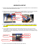
-6- UNCRATE & SETUP 1. Remove shrink wrap and upper crating structure. Remove the two black shelves and work table from the skid. Locate the box that contains the casters. 2. Attach the casters to the mounting plates using the supplied hardware. The swivel casters should be mounted on the same end of the machine as the hydraulic cylinder and digital readout. #3 Sling Position #2 Swivel Casters This End 3.
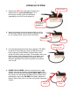
-7- HYDRAULIC SYSTEM Pump Assembly 1. Remove the RED Plug in the pump assembly and replace with the supplied BLACK plug. This is the reservoir venting system and damage or inoperability may result if not changed out. RED Plug should be changed to BLACK Plug 2. Attach the hydraulic hose to the pump. Attach an air line fitting for your shop air to other end of the pump. Be sure to use a quality thread sealer on both connections Hydraulic Hose Air Hose Push Down to Release Pressure 3.
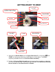
-8- GETTING READY TO BEND Pressure Roller Assembly U Saddle & Pin Assembly or Adjustable Saddle Assembly Pressure Roller Release Handle Start Mark Follow Bar Square Drive Shaft Rotation Direction Bender Shoe Pressure Roller Assembly “U” Shims Pressure Roller in Released Position Pressure Roller in Bend Position 1. Slide the main Bender Shoe over the Square Drive Shaft. Be sure that the MB and START are facing up and that they are positioned as shown above.
-93. Move the Pressure Release Handle to the RELEASED position and place the tubing (which has already been marked with the bend start points) into the Bender Shoe with the first bend start mark aligned with the START arrow on the Bender Shoe. Slip the “U” Saddle or Adjustable Saddle over the tubing and the Bender Shoe. Align the holes and install the pin, if using the adjustable saddle, tighten down the clamp knob.
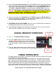
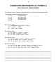
- 10 - CORRECTED MATHEMATICAL FORMULA FOR HYDRAULIC TUBING BENDER The following formula should be used to determine the start point for each required bend. The example will be for a Double Bevel Bend L1 = 26 25 degree angle L2 = 15 65 degree angle L3 = 39 65 degree angle L4 = 15 25 degree angle L5 = 26 Bend #1 Start Point: L1 – ½ developed length (DL25) – ½ (Gain) 26” – ½ (3.064”) – ½ (.050) 26” – 1.532” - .025” = 24.448 Bend #2 Start Point: L1 + L2 – Gain 1 – ½ (DL65) – ½ (Gain 2) 26 + 15 - .050 –1/2 (7.
- 11 - GAIN FACTORS Degree of Bend Multiplier Degree of Bend Multiplier Degree of Bend Multiplier 1 2 3 4 5 6 7 8 9 10 11 12 13 14 15 16 17 18 19 20 21 22 23 24 25 26 27 28 29 30 .0000 .0000 .0000 .0000 .0000 .0001 .0001 .0003 .0003 .0005 .0006 .0008 .0010 .0013 .0015 .0018 .0022 .0026 .0031 .0036 .0042 .0048 .0055 .0062 .0071 .0079 .0090 .0100 .0111 .0126 31 32 33 34 35 36 37 38 39 40 41 42 43 44 45 46 47 48 49 50 51 52 53 54 55 56 57 58 59 60 .0136 .0150 .0165 .0181 .0197 .0215 .0234 .0254 .
- 12 - TABLE FOR OFFSET MULTIPLIER Degree of Bend 1 2 3 4 5 6 7 8 9 10 11 12 13 14 15 16 17 18 19 20 21 22 23 24 Multiplier 57.30 28.65 19.11 14.33 11.47 9.57 8.21 7.18 6.39 5.76 5.24 4.81 4.45 4.13 3.86 3.63 3.42 3.24 3.07 2.92 2.79 2.67 2.56 2.46 Degree of Bend 25 26 27 28 29 30 31 32 33 34 35 36 37 38 39 40 41 42 43 44 45 46 47 48 Multiplier 2.37 2.28 2.20 2.13 2.06 2.00 1.94 1.89 1.84 1.79 1.74 1.70 1.66 1.62 1.59 1.56 1.52 1.49 1.46 1.44 1.41 1.39 1.37 1.
- 13 - DEVELOPED LENGTH DEVELOPED LENGTH = .0175 X DEGREE OF BEND X RADIUS EXAMPLE: FIND THE DEVELOPED LENGTH OF A 70 DEGREE BEND USING AN 8 INCH RADIUS. DEVELOPED LENGTH = .0175 X 70 X 8 = 9.
- 14 -
- 15 -
- 16 -
- 17 -
- 18 -
- 19 -
- 20 - \
- 21 -
- 22 -
- 23 - MAINTANANCE WARNING Be sure the cylinder is completely retracted and that the hydraulic pump is disconnected before servicing this machine. • There are two bearing blocks that are greaseable. These can be accessed from under the top by looking in from the opening. The lower fitting is visible and the upper fitting is up between the frame rails of the bender. A few pumps of high quality grease every month is recommended for average use.
- 24 - MAINTENANCE Inspecting The Hydraulic Fluid Level Check the fluid level in the reservoir after every 10 hours of use. Drain and replenish the reservoir with Power Team hydraulic fluid after every 300 hours of use approximately. Air Hydraulic Pump For pumps with a 105 cubic inch (1.71) reservoir capacity Electric Hydraulic Pump For pumps with a 2 gallon (7.61) reservoir capacity The fluid level should be 1/2 inch (12.7 mm) from the filler / vent cap with all cylinders retracted.
- 25 - OPTIONAL EQUIPMENT HYDRAULIC 180° TUBE BENDER SHOE LIST ROUND TUBE SIZE C/L RADIUS PART # 3/4” 4” 1” 4” 2500-S09 2500-S08 1-1/8” 4” 2500-S07 1-1/4” 5” 2500-S06 1-3/8” 5” 2500-S05 1-1/2” 6” 2500-S04 1-5/8” 7” 2500-S03 1-3/4” 7” 2500-S02 1-3/4” 8” 2500-S01 2” 8” 2500-S00 3/4” 4” 2500-S11 1” 4” 2500-S10 1-1/8” 4” 2500-S12 1-1/4” 5” 2500-S13 1-1/2” 6” 2500-S14 1-3/4” 7” 2500-S15 1-3/4” 8” 2500-S16 2” 8” 2500-S18 1” 5” 2500-S30 1-1/4” 6” 2500-
- 26 - Adjustable Saddles for 90° & 180° Hydraulic Benders Saddle eliminates the need for individual saddles for each tubing size. Two sizes handle 5/8” to 1-3/4” Round & Square Tubing.
- 27 - Bend Protractors 2100-4 4" Protractor Assembly 2100-5 5" Protractor Assembly 2100-6 6" Protractor Assembly 2100-7 7" Protractor Assembly 2100-8 8" Protractor Assembly 2100 4" Thru 8" Protractor Set Bend Stop for Hydraulic 180° Tube Bender 2500-400 Bend Stop Kit for 180° Bender
- 28 - BEND-TECH EZ Designed for simple 2d parts! 900-510 Bend-Tech EZ Software BEND-TECH EZ-3D Designed for 3d bending, with 360 degree part rotation! 900-511 Bend-Tech EZ-3D Software BEND-TECH PRO Full 3d Assembly & Manufacturing Instructions, plus all EZ features! 900-512 Bend-Tech Pro Software 900-513 Bend-Tech SE Software