NOT CURRENT -1- Operating Manual Model # 2500 180° Hydraulic Bender CAUTION: Read and Understand These Operating, Servicing, and Safety Instructions, Before Using This Machine. 1-800-467-2464 10 Cooperative Way Wright City, MO 63390 P.O. Box 110 Foristell, MO 63348 1-636-745-7757 Fax 1-636-745-2874 www.mittlerbros.
-2- SAFETY The purpose of the safety section of this manual is to inform operators and maintenance personnel of the precautions to be taken while operating or servicing the machine. The following are a few basic guidelines to follow, but as with any type of machinery good judgment and a safe attitude should be applied at all times. 1 Always disconnect power, lock-out and tag-out machine per OSHA regulations before attempting to service this machine. 2.
-3- HYDRAULIC SAFETY PRECAUTIONS WARNING General Operation • • • • • • • • • • All WARNING statements must be carefully observed to help prevent personal injury. Before operating the pump, all hose connections must be tightened with the proper tools. Do not over tighten. Connections should only be tightened securely and leak-free. Over tightening can cause premature thread failure or high pressure fittings to split at pressures lower than their rated capacities.
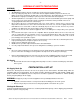
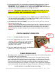
-4- HYDRAULIC SYSTEM Pump Assembly 1. Remove the RED Plug in the pump assembly and replace with the supplied BLACK plug. This is the reservoir venting system and damage or inoperability may result if not changed out. RED Plug should be changed to BLACK Plug 2. Attach the hydraulic hose to the pump. Attach an air line fitting for your shop air to other end of the pump. Be sure to use a quality thread sealer on both connections Hydraulic Hose Air Hose Push Down to Release Pressure 3.
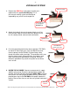
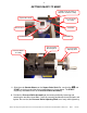
-5- GETTING READY TO BEND U Saddle & Pin Assembly or Adjustable Saddle Assembly Square Drive Shaft Pressure Roller Assembly Bender Shoe Start Mark Rotation Direction Follow Bar Pressure Roller Mounting Block Pressure Roller Assembly Pressure Roller Adjusting Shaft 1. Slide the main Bender Shoe over the Square Drive Shaft. Be sure that the MB and START are facing up and that they are positioned as shown above. The START engraving should be closest to the Pressure Roller Assembly. 2.
-63. Place the tubing (which has already been marked with the bend start points) into the Bender Shoe with the first bend start mark aligned with the START arrow on the Bender Shoe. Slip the U Saddle over the tubing and the Bender Shoe. Align the holes up and install the Pin. See diagram at top of Page 8 for details. CAUTION: THE PIN MUST BE COMPLETELY THROUGH BOTH SIDES OF THE U SADDLE! FAILURE TO HAVE PIN COMPLETELY INSTALLED MAY RESULT IN EQUIPMENT DAMAGE AND / OR PERSONEL INJURY! 4.
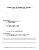
-7- CORRECTED MATHEMATICAL FORMULA FOR HYDRAULIC TUBING BENDER The following formula should be used to determine the start point for each required bend. The example will be for a Double Bevel Bend L1 = 26 25 degree angle L2 = 15 65 degree angle L3 = 39 65 degree angle L4 = 15 25 degree angle L5 = 26 Bend #1 Start Point: L1 – ½ developed length (DL25) – ½ (Gain) 26” – ½ (3.064”) – ½ (.050) 26” – 1.532” - .025” = 24.448 Bend #2 Start Point: L1 + L2 – Gain 1 – ½ (DL65) – ½ (Gain 2) 26 + 15 - .050 –1/2 (7.
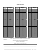
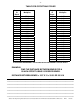
-8- GAIN FACTORS Degree of Bend Multiplier Degree of Bend Multiplier Degree of Bend Multiplier 1 2 3 4 5 6 7 8 9 10 11 12 13 14 15 16 17 18 19 20 21 22 23 24 25 26 27 28 29 30 .0000 .0000 .0000 .0000 .0000 .0001 .0001 .0003 .0003 .0005 .0006 .0008 .0010 .0013 .0015 .0018 .0022 .0026 .0031 .0036 .0042 .0048 .0055 .0062 .0071 .0079 .0090 .0100 .0111 .0126 31 32 33 34 35 36 37 38 39 40 41 42 43 44 45 46 47 48 49 50 51 52 53 54 55 56 57 58 59 60 .0136 .0150 .0165 .0181 .0197 .0215 .0234 .0254 .0276 .
-9- TABLE FOR OFFSET MULTIPLIER Degree of Bend 1 2 3 4 5 6 7 8 9 10 11 12 13 14 15 16 17 18 19 20 21 22 23 24 Multiplier 57.30 28.65 19.11 14.33 11.47 9.57 8.21 7.18 6.39 5.76 5.24 4.81 4.45 4.13 3.86 3.63 3.42 3.24 3.07 2.92 2.79 2.67 2.56 2.46 Degree of Bend 25 26 27 28 29 30 31 32 33 34 35 36 37 38 39 40 41 42 43 44 45 46 47 48 Multiplier 2.37 2.28 2.20 2.13 2.06 2.00 1.94 1.89 1.84 1.79 1.74 1.70 1.66 1.62 1.59 1.56 1.52 1.49 1.46 1.44 1.41 1.39 1.37 1.
- 10 - DEVELOPED LENGTH DEVELOPED LENGTH = .0175 X DEGREE OF BEND X RADIUS EXAMPLE: FIND THE DEVELOPED LENGTH OF A 70 DEGREE BEND USING AN 8 INCH RADIUS. DEVELOPED LENGTH = .0175 X 70 X 8 = 9.
NOT CURRENT - 11 -
NOT CURRENT - 12 - MAINTANANCE WARNING Be sure the cylinder is completely retracted and that the hydraulic pump is disconnected before servicing this machine. • There are two bearing blocks that are greaseable. These can be accessed from under the top by looking in from the opening. The lower fitting is visible and the upper fitting is up between the frame rails of the bender. A few pumps of high quality grease every month is recommended for average use.
NOT CURRENT - 13 - OPTIONAL EQUIPMENT 180 DEGREE BENDER SHOE LIST ROUND TUBE SIZE C/L RADIUS PART # 3/4” 4” 1” 4” 2500-S09 2500-S08 1-1/8” 4” 2500-S07 1-1/4” 5” 2500-S06 1-3/8” 5” 2500-S05 1-1/2” 6” 2500-S04 1-5/8” 7” 2500-S03 1-3/4” 7” 2500-S02 1-3/4” 8” 2500-S01 2” 8” 2500-S00 3/4” 4” 2500-S11 1” 4” 2500-S10 1-1/8” 4” 2500-S12 1-1/4” 5” 2500-S13 1-1/2” 6” 2500-S14 1-3/4” 7” 2500-S15 1-3/4” 8” 2500-S16 2” 8” 2500-S18 1” 5” 2500-S30 1-1/4” 6” 2
- 14 - Adjustable Saddles For 2500 180° Hydraulic Bender 5/8” TO 1-1/8” OD. Adjustable Saddle........2500-300 1-1/48” TO 1-3/4” OD. Adjustable Saddle...2500-301 This new style saddle eliminates the clutter of a saddle for every size. Two saddles cover all sizes of round & square tube from 5/8” to 1-3/4”. The adjustable locking block allows you to securely snug the tubing to the shoe and give you consistent compound and multi plane bends. This new design also eliminates the stuck saddle syndrome.
- 15 - NOTES ____________________________________________________________________________________________ ____________________________________________________________________________________________ ____________________________________________________________________________________________ ____________________________________________________________________________________________ ____________________________________________________________________________________________ _________________________________
- 16 - 180° Hand Tubing Bender Ultimate Tubing Notcher Power Bead Rollers Hydraulic Tubing Bender 1-800-467-2464 Bench Press www.mittlerbros.com \\Mbserver01\Engineering\Product\Product Documentation\2500 180 HYD Bender\manual\2500 Owners Manual.doc REV.