DLP™ PROJECTOR MODEL UD740U User Manual UD740U This User Manual is important to you. Please read it before using your projector.
CAUTION RISK OF ELECTRIC SHOCK DO NOT OPEN CAUTION: TO REDUCE THE RISK OF ELECTRIC SHOCK, DO NOT REMOVE COVER (OR BACK) NO USER-SERVICEABLE PARTS INSIDE REFER SERVICING TO QUALIFIED SERVICE PERSONNEL. The lightning flash with arrowhead symbol within an equilateral triangle is intended to alert the user to the presence of uninsulated “dangerous voltage” within the product’s enclosure that may be of sufficient magnitude to constitute a risk of electric shock.
Contents Important safeguards.........................................................................................................................4 Overview.............................................................................................................................................6 Remote control...................................................................................................................................8 Installation .................................................
Important safeguards Please read all these instructions regarding your projector and retain them for future reference. Follow all warnings and instructions marked on the projector. 10. Power sources This projector should be operated only from the type of power source indicated on the marking label. If you are not sure of the type of power, please consult your appliance dealer or local power company. 11.
Important safeguards (continued) WARNING: Do not use the projector with condensation on it. It can lead to breakdown or other failure. Unplug immediately if there is something wrong with your projector. Do not operate if smoke, strange noise or odor comes out of your projector. It may cause fire or electric shock. In this case, unplug immediately and contact your dealer. Place of installation For safety’s sake, do not use the projector at any place subjected to high temperature and high humidity.
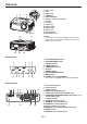
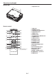
Overview 1 2 3 1 2 3 4 5 6 7 8 9 10 11 12 13 14 4 5 6 789 10 12 13 Lamp cover Lens FOCUS ring ZOOM ring LENS SHIFT dial Remote control sensor (front) Speaker Lock bar Intake vent Control panel Exhaust vent Power jack Terminal panel Kensington Lock Caution: • Do not replace the lamp immediately after using the projector because the lamp would be extremely hot and it may cause burns.
Overview (continued) Bottom side 1 Adjustment feet 1 Remote control ON STANDBY MAGNIFY ASPECT 12 1 2 3 4 5 6 VOL UP EFFICIENT MODE DOWN KEYSTONE 3D AUTO POSITION MENU ENTER 7 8 9 10 11 AV MUTE VIEWER VIDEO 1 USB DISP. S-VIDEO 2 LAN DISP. DVI 15 16 17 FREEZE COMPUTER UNPLUG 13 14 HDMI 18 19 20 21 This model does not have this function.
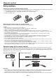
Remote control Battery installation Use two (AA, R6) size batteries. Inserting the batteries into the remote control 1. Remove the back cover of the remote control by pushing the battery compartment door in the direction of the arrow. 2. Load the batteries making sure that they are positioned correctly (+ to +, and - to -). • Load the batteries from - spring side, and make sure to set them tightly. 3. Replace the back cover.
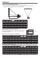
Installation Screen size and projection distance Refer to the following tables to determine the screen size and projection distance. • The figures in the tables are approximate and may be slightly different from the actual measurements. • The lens shift height shows distances from the factory default position.
Installation (continued) Front projection, ceiling mounting kit. (Don’t use screw holes without arrow marks.) In this case, make sure that the screw is inserted in the projector at least 5 mm. The length of the screw should be 20 mm or shorter. Also make sure that no electrical current is flowing in the mount kit due to current leakage or other cause. For ceiling mounting, you need the ceiling mount kit designed for this projector. Ask a specialist for installation. For details, consult your dealer.
Basic connections This projector can be connected with various devices such as a VCR, video camera, videodisc player, and personal computer that have analog RGB output connectors. Important: • Make sure that the connected device is turned off before starting connection. • Plug in the power cords of the projector and the connected devices firmly. When unplugging, hold and pull the plug. Do not pull the cord.
Basic connections (continued) Connection (for video equipment having an HDMI terminal) Equipment having an HDMI terminal To HDMI terminal HDMI HDMI (with HDMI logo) cable (option) Important: • Use a commercially available HDMI (with HDMI logo) cable. • You don’t have to connect any cable for audio input. You can input video and audio using an HDMI cable only.
Basic connections (continued) Projector + Computer For computer with mini D-SUB Computer cable COMPUTER/ COMPONENT VIDEO IN Necessary when outputting to both a PC monitor and the projector. Computer Computer cable (option) To monitor port MONITOR OUT AUDIO IN-1 or IN-2 AUDIO OUT Audio cable (option) PC audio cable (option) To PC audio output For analog connection: 1. Connect one end of the supplied computer cable to the COMPUTER/COMPONENT VIDEO IN terminal (1, 2) of the projector. 2.
Preparation Preparation for projection Important: • When Standby Mode of the Efficient Mode menu in the Installation menu is set to Speaker Out or Monitor Out, the fans rotate at very low speed during standby after plugging the power cord (with 5 second high speed rotation at the beginning) and after turning off the lamp. This is to cool down the projector operating various functions during standby and is not a malfunction. (When Standby Mode is set to Low or LAN, the fans stop during standby.) 1.
Preparation (continued) Adjustment of the projection angle • When the projector is projecting images where acceleration is present, such as in a vehicle and aircraft, the automatic keystone adjustment may not function correctly. In such a case, set Auto Keystone in the Installation menu to Off and correct the keystone manually. • You can correct the vertical keystones. However, their adjustment ranges are limited in such correction.
Basic operation 4 3 6 ON STANDBY MAGNIFY ASPECT VOL UP EFFICIENT MODE DOWN KEYSTONE 1, 2 3D AUTO POSITION MENU ENTER AV MUTE VIEWER FREEZE VIDEO 1 COMPUTER UNPLUG USB DISP. 5 LAN DISP. DVI 5 HDMI 3, 1, 2 Power-on • The projector starts warming up when the POWER button is pressed. During the warm-up process, images may appear dark and no commands are accepted. • By blinking red, the STATUS indicator indicates that the lamp should be replaced soon.
Basic operation (continued) Direct Power OFF • To avoid permanently imprinting a fixed image onto your projector, please do not display the same stationary images for long period. 6. Adjust the image size by turning the zoom ring. 7. Adjust the vertical position of the displayed image by turning the LENS SHIFT dial. • If necessary, adjust the focus and zoom again. When fine streaks are seen on projected images This is due to interference with the screen surface and is not a malfunction.
Basic operation (continued) AV mute When connecting to a laptop computer: The video and audio signals are temporarily muted when the AV MUTE button is pressed. To cancel muting, press the AV MUTE button again. When this projector is connected to a laptop computer, there may be times when images may not be projected. When it occurs, set the computer so that it can output signals externally. The procedure varies across computers in use. See the instruction manual of your computer.
Basic operation (continued) Watching 3D content To view 3D images: You can enjoy 3D content with this projector. In order to watch 3D content, you need to have the following items: • 3D images inputted from a computer, DVD player, Blu-ray player, etc. • DLP™ Link™ active 3D glasses Preparation: • Switching the 3D mode (such as 3D setting system) of the player may be required when projecting 3D images from the player supporting 3D display. Read the user manual of the player for details. 1.
Basic operation (continued) • If the viewing distance is nearer than the recommended distance, it will cause physical discomfort and eye fatigue. • Watch the contents in front of the screen, not at big angle. If you are viewing the screen at big angle, you may not be able to view 3D contents correctly. • If you are not viewing 3D contents correctly, check to see if the 3D glasses are powered on or adequately charged. See the instruction manual of the 3D glasses for more information.
Menu operation You can make various settings using the displayed menus. Picture Image Brightness Contrast Color Temp. Color Management Aspect Ratio Input Level 3D 3D Sync Invert *1 *1 *1 Video Image Color Sharpness Tint Signal Memory Call *1*2 Resolution (Memorize) *1*2 H. Position V.
Menu operation (continued) How to set the menus 5. Set the selected item by pressing the or button. 1. Press the MENU button. • The Main Menu appears on the screen. Installation Efficient Mode The item being selected is displayed in red letters on a blue background.
Menu operation (continued) Menu items Set the following items provided in the respective menus. Picture menu Picture Auto Image 0 Brightness 0 Contrast Mid Color Temp. Color Management Red Aspect Ratio Normal Auto Input Level Auto 3D 3D Sync Invert Off Adjust MENU Exit Select ITEM Image SETTING Auto Theater Presentation Standard Black Board White Board Brightness Contrast Color Temp.
Menu operation (continued) Video Image menu Video Image Color 0 Sharpness 0 Tint 0 Adjust MENU Exit Select ITEM Color SETTING ±10 Sharpness Tint ±5 ±10 • • FUNCTION Adjusts the color tone of projected images. (See page 31.) You cannot select this setting when Computer1, Computer2, or HDMI is selected as the input source. Adjusts the sharpness of projected images. (See page 31.) Adjusts the color tint of projected images. (See page 31.
Menu operation (continued) Signal menu Resolution (Memorize) Signal Memory Call Resolution (Memorize) Auto 1024 x 768 User H. Frequency 60.00 kHz V. Frequency 60.00 Hz Clamp Position 1 Clamp Width 1 H. Position 0 H. Pixels 1024 LPF V. Position 0 V.
Menu operation (continued) Signal menu (continued) • • • • • • • Menus may not be displayed partially depending on the settings of H. Pixels and V. Lines in the Resolution (Memorize) menu. In this case, execute AUTO POSITION. (See page 17.) Horizontal strips may appear in the enlarged projected image, though these conditions are not a malfunction. When you change the value of the horizontal or vertical position drastically, noise may appear.
Menu operation (continued) Installation menu Installation Efficient Mode Efficient Mode OK Lamp Mode Standard Menu Position Upper Left Standby Mode Low Image Reverse Off Auto Power Off 5Min Auto Power On Off Auto Keystone Off Test Pattern Language Reset All Adjust Adjust MENU Exit Select Cross Hatch English OK MENU Exit Select ITEM Efficient Mode Lamp Mode Standby Mode SETTING OK Standard Low Low LAN Speaker Out Monitor Out Auto Power Off Menu Position Image Reverse Off / 5-60 Min
Menu operation (continued) Option menu Option Password OK Cinema Mode Auto Video Signal Auto Signal Detect Normal Auto Set Up Original Splash Screen Back Color Blue AV Mute Mode Black Closed Caption Off Adjust MENU Exit Select ITEM Password Cinema Mode SETTING OK Auto / Off Video Signal 8 options Signal Detect Normal Enhanced Set Up Auto Off 3.75% / 7.
Menu operation (continued) Network Config menu IP Config Network Config Wireless Setting On Projector Name SET DHCP Network Certification On IP Address 169 - 254 - 0 - 220 Network Password OK Subnet Mask 255 - 255 - 0 - 0 Encryption IP Config OK Default Gateway 169 - 254 - 0 - 1 Wireless Setup Wireless Setting OK MAC Address AMX Device Discovery Off DHCP Function Network Initialization OK Start IP Address 169 - 254 - 0 OK End IP Address 169 - 254 - 254 - 254 OK Netwo
Menu operation (continued) Information menu Information 2000H Lamp Time Computer1 Input Resolution 1024x768 H. Frequency 60.00 kHz V. Frequency 60.00 Hz 293 H. Position 35 V. Position 1344 Tracking 3Wire Sync. Type MENU Exit ITEM Lamp Time DESCRIPTION Resolution This menu shows a lamp operating time (hour) calculated assuming that Lamp Mode is Low. • When the Lamp Mode is Standard, this menu shows a longer lamp operating time than the actual time.
Image adjustment To adjust the tone of white (Color Temp.): To adjust the brightness (Contrast and Brightness): You can make adjustments for the brightness of the projected image using the menu. (See page 22 for menu setting.) 1. Display the Picture menu. 2. Select Contrast or Brightness by pressing the or button. 3. Adjust the selected item by pressing the or button. To cancel the menu: 4. Press the MENU button. You can select a preset color temperature (white tone) using the menu.
Image adjustment (continued) Image Color Management You can set user-defined values for the brightness and hue using the menu. (See page 22 for menu setting.) 1. Display the Picture menu. 2. Select Image by pressing the or button. 3. Select User by pressing the or button. 4. Press the ENTER button. • The Image User menu appears. You can individually adjust the tone of red, green, blue, cyan, yellow and magenta using the menu. 1. Display the Picture menu. 2.
Image adjustment (continued) How to adjust the computer image This projector automatically selects a proper signal format according to the type of video signal supplied from the computer. However, video signals from the computer may not be projected correctly depending on the types of the computer and images to be projected. In such a case, make adjustment according to the flowchart below. When the size and position of the computer image are not correct.
Image adjustment (continued) How to adjust the image supplied from the computer using the menu: Simple method to adjust the image position Carry out the following procedures according to the symptoms. To adjust the horizontal position: 1. Align the left edge of the image with the left side of the screen by adjusting H.Position. Then, align the right edge of the image with the right side of the screen by adjusting Tracking. 2. Repeat step 1 to complete the adjustment of the horizontal position.
Network settings Enabling or disabling the network certification You can set the network of the projector using the menu. You can select whether or not to certify the network communication using the network password. (See page 22 for menu setting.) 1. Display the Network Config menu. 2. Press the or button to select Network Certification.
Network settings (continued) 5. Select OK, and NEW NETWORK PASSWORD screen appears if the entered password is correct. • If the entered password is not correct, the CURRENT NETWORK PASSWORD screen appears again. 3. Press the ENTER button. • The IP Config menu appears.
Network settings (continued) Subnet Mask settings Start IP Address setting 1. Display the IP Config menu. 2. Press the or button to select Subnet Mask. 1. Display the IP Config menu. 2. Press the or button to select Start IP Address. Subnet Mask 255 - 255 - 0 - 0 Start IP Address 3. Press the ENTER button. • The first octet is selected.
Network settings (continued) Wireless Setting Channel setting (See page 22 for menu setting.) 1. Display the Network Config menu. 2. Press the or button to select Wireless Setting. 1. Display the Wireless Setting menu. 2. Press the or button to select Channel. Auto Channel OK Wireless Setting 3. Press the or button to select Auto or 1 to 11. • To cancel the setting, press the MENU button. 3. Press the ENTER button. • The Wireless Setting menu appears.
Network settings (continued) 8. Select OK to complete the setting with the Encryption and KEY stored. Select CANCEL to complete the setting without storing. • The display returns to the Wireless Setting menu after selecting CANCEL. • The number of characters of KEY varies depending on the Encryption setting.
Advanced display utilities USB Display Installation of driver Supported OS’s are as follows: • Windows XP • Windows Vista • Windows 7 • Mac OS X 10.5 or later Installing USB Display driver 1. Via the Finder, open [USB_DISPLAY] and doubleclick [USB Display.pkg]. When using Mac OS X, install the driver after connecting the projector and the computer using a USB cable for the first time. Once you have installed the driver, you don’t need to install it again.
Advanced display utilities (continued) LAN Display Operation You can project the computer images inputted via a wired or wireless LAN. Starting USB Display projection 1. Select a USB Display input by pressing the USB DISP. button on the remote control or the COMPUTER button on the projector. • Each time you press the COMPUTER button, the input source is switched between Computer1, Computer2, HDMI, LAN Display, USB Display and PC Less Presentation.
Advanced display utilities (continued) Connection When using Mac OS X Connect the projector and the computer either by using a commercially available LAN cable or USB wireless LAN adapter. 1. Copy “LAN Display System_v300.dmg” contained in the TOOLS folder of CD-ROM to the hard disk of your computer. 2. Double-click “LAN Display System_v300.dmg” on the hard disk. • The volume is mounted. 3. Drag and drop “LAN Display System” and “SidePadLite” into the [Applications] folder.
Advanced display utilities (continued) • Stop button: Stops the projection. • Freeze button: Freezes the projected image. • Menu button: Displays the menu window. (See the next step for details.) • Exit button: Exits the LAN Display System. Starting the LAN Display System 2. Click the LAN Display System icon “ ” to execute the program. • The program starts to search for projectors automatically. • During searching for projectors, Searching icon is displayed. 4.
Advanced display utilities (continued) Installing the Virtual Audio driver Important: • To use this function with Windows XP, the attached Virtual Audio driver must be installed. • To use this function with Mac OS X, attached Soundflower must be installed. • About Displays the version information of the LAN Display System. • Exit Exits the LAN Display System. To use “Send Audio to Display” with Windows XP, install the Virtual display driver as follows.
Advanced display utilities (continued) Using SidePad function 2. On the computer, click the Menu button on the main user interface to display the menu window and select [Launch SidePad -> MirrorOp Receiver]. • Computer images are transferred to the tablet computer and you can operate the computer from the tablet computer. While computer images are projected with the LAN Display, you can operate the computer from the tablet computer.
Advanced display utilities (continued) WiFi-Doc 2. Turn on Wi-Fi. • Access points will be listed on the screen. 3. Tap the projector’s SSID. Via a wireless LAN, you can transfer the images of the Microsoft PowerPoint, Word, Excel, PDF, TXT, or JPEG format stored in the tablet computer to the projector and project them controlling with the tablet computer. To use WiFi-Doc, you need to install the free software “WiFi-Doc (Bundle Version)” to the tablet computer.
Advanced display utilities (continued) 4. Select a file to be projected by tapping its name. • The image of the selected file is displayed. 4. Select a file to be projected by tapping its name. • The image of the selected file is displayed. 5. Operate the image by touching the tablet screen. 5. Operate the image by touching the tablet screen. • Flick the screen to move to the previous or next page. • Pinch the screen for zooming in or out.
Advanced display utilities (continued) Thin client 4. Click [Remote settings]. Projecting the desktop screen of a remote computer connected via a network onto the projector, you can remotely control the remote computer through the projector. To use the thin client function, you need to install the software “ThinClient.exe” contained in the attached CD-ROM.
Advanced display utilities (continued) In Windows XP 1. Select [Start]-[Control Panel]. 2. Click [Performance and Maintenance]. • When using Classic View, double-click the System icon and go to step 4. 3. Click [System]. • The “System Properties” window is displayed. 4. Click the [Remote] tab and check the [Allow users to connect remotely to this computer] checkbox. 5. Click [Select Remote Users...]. • The “Remote Desktop Users” window is displayed. 6.
Advanced display utilities (continued) Connection 3. Click the [Exceptions] tab, check the [Remote Desktop] checkbox and click [OK]. Connect the projector and the computer using a commercially available LAN cable. Connect a USB mouse and USB keyboard to the USB-A terminal on the projector. Computer To LAN terminal LAN cable (option) In Windows XP 1. Select [Start]-[Control Panel]. 2. Click [Network and Internet Connections].
Advanced display utilities (continued) Connecting the projector to the computer For the following operation, use the USB device such as a mouse or keyboard connected to the projector. • If you connect to a computer installed with Windows XP, Windows Vista or Windows 7 that any other user has already logged on, “Another user is currently logged on to this computer.” will be displayed.
Advanced display utilities (continued) Client Access License (CAL) Device CAL With Device CAL, you purchase CALs according to the number of devices accessing to the host, regardless of the number of users who access the host via thin client computer or projector. Therefore Device CAL is recommended for the case that multiple operators share a thin client computer or projector. An application allowing multiple users to share a single operation system requires the standard Microsoft Windows server licenses.
Advanced display utilities (continued) PC Less Presentation Installing PtG Converter-Lite Before starting installation, be sure to read “ReadMe. txt” contained in the CD-ROM. Copy “PtG ConverterLite_v200.exe” contained in the TOOLS folder of CDROM to the hard disk of your computer. 1. Double-click “PtG Converter-Lite_v200.exe”, and start up the installer of the PtG Converter-Lite. 2. Follow the on-screen instructions to install the software.
Advanced display utilities (continued) 3. Select the PPT file you want to convert, and click [Open]. • The screen for specifying the file destination and name appears. Performing the PC Less Presentation Selecting a PC Less Presentation input 1. Press the VIEWER button on the remote control or the COMPUTER button on the projector. • Each time you press the COMPUTER button, the input source is switched between Computer1, Computer2, HDMI, LAN Display, USB Display and PC Less Presentation.
Advanced display utilities (continued) Displaying with AutoRun function 5. Create an “AUTORUN” folder in the root directory of the USB device using a computer or other. 6. Save a PtG file or JPEG files in the AUTORUN folder. Important: • The AutoRun function supports single PtG file only. The PtG file located on the top by sorting is played if multiple PtG files exists in AUTORUN folder. 7. Connect the USB device to the USB-A terminal.
Advanced features Freeze Magnify By pressing the MAGNIFY button on the remote control, you can magnify the image to view the details. • The MAGNIFY mode doesn’t function with some input signals. For details, see page 70. • The MAGNIFY mode doesn’t work with video or S-video signal. To stop the motion in the image temporarily (or to display a still image): Press the FREEZE button on the remote control. • The image freezes temporarily.
Advanced features (continued) Password lock To enable or disable password lock: This projector provides the password lock function that is intended to prevent wrong operations by children and set controlled access for specified users. If the password lock is enabled, when the projector is turned on, the startup screen (or splash screen) will appear and stay on the screen until the password is entered. When the password is entered, the startup screen will switch to the regular operation screen.
Advanced features (continued) Supervising and controlling by computer About PJLink™ • To use PJLink™ function, the PJLink™ application software is required. • To use this function, set the network certification properly according to the setting of the network application to be used. (See page 35.) • For the specifications of PJLink™, access to the Web site of Japan Business Machine and Information System Industries Association (JBMIA). (http://pjlink.jbmia.or.
Advanced features (continued) Connection For details of the connection, see “LAN Control Utility User Manual” in the CD-ROM. When Standby Mode of the Efficient Mode menu in the Installation menu of the projector is set to Low, the LAN network is disabled. To enable the LAN network, set Standby Mode to LAN. (See page 27.) Configure the initial network settings first. You can configure the initial settings using the projector menu (see pages 35 to 39) or ProjectorView Global+.
Lamp replacement This projector is equipped with a lamp to project images. This lamp is a consumable. It may burn out or its brightness may decrease during use. In such cases, replace the lamp with a new one as soon as possible. Be sure to replace the lamp with a new lamp separately sold that is exclusive to this projector. Contact your dealer for purchase of the lamp. 3. Loosen the two screws (d) of the lamp unit, and then pull out the lamp unit (f) by the handle (e).
Lamp replacement (continued) Reset of the lamp operation time 3. Assemble the lamp replacement attachment by folding two taping portions (g) and two cutout portions (h) along the folding line as the figure. (h) (g) Plug in the power cord, and reset the lamp operation time by keep pressing the , , and POWER buttons on the control panel simultaneously for 3 seconds. Important: • Unless these three buttons are pressed at the same time, the lamp operation time isn’t reset.
Troubleshooting Before asking for repair of the projector, check the following. If the symptom persists, stop using the projector, be sure to unplug the power plug, and then contact your dealer. No image appears on the screen. Problem Solution Power can not be turned on. • Check whether the indicators are on or off and how they are lightning. POWER Off STATUS Off Solution • Connect the power cord to the projector. • Plug the power cord into a wall outlet.
Troubleshooting (continued) No image appears on the screen. (continued) Problem Solution The screen for entering the password appears. • Password in the Password menu has been set to On to enable the password lock. Enter the password or contact the person in charge of management of the projector. (See page 57.) “No signal” is displayed. • Turn on the power of the connected device, or check whether there is something wrong with the connected device. • Check whether the external device output signals.
Troubleshooting (continued) Images are not displayed correctly. (continued) Problem Solution Projected images become wavy. • Connect the plugs of the cables to external devices securely. • Keep the projector away from equipment generating interfering radio waves. • When the keystone adjustment is carried out, the image may not be displayed correctly because of the type of input signal. This isn’t a product malfunction.
Troubleshooting (continued) Others (continued) Problem Solution The remote control doesn’t function easily or at all. • Check that the batteries are loaded in the remote control or the batteries are not weak. (See page 8.) • Check that the remote control sensor isn’t exposed to direct sunlight or fluorescent light. (See page 8.) • Use the remote control within its operation range. (See page 8.) • Use the remote control at least 10 cm away from the projector.
Troubleshooting (continued) If the following problem occurs after the lamp is replaced, check the following first. Problem Solution The projector does not turn on. • Fit the lamp cover securely. (See page 60 or 61.) • Reset the lamp operating time. (See page 61.) The STATUS indicator blinks. • Reset the lamp operating time. (See page 61.) Maintenance Warning: • Do not use flammable solvents (benzene, thinner, etc.) and flammable aerosols when cleaning the projector body and lens.
Indicators This projector has two indicators, each of which shows the operation condition of the projector. The following offer solutions to possible problems. If these problem persist, turn the projector off and consult your dealer. STATUS indicator POWER indicator Normal condition POWER STATUS Off Steady red CONDITION Stand-by Lamp stand-by for power-off The power cannot be turned on by pressing the POWER button.
Specifications Type Model Rated power supply Power consumption Display Technology Colors Projection lens Light source lamp Picture size PC compatibility Video compatibility Speaker S-video input Video input Audio input Analog RGB input HDMI input Control connector Outside dimensions Weight Length of power cord Temperature, humidity (performance guaranteed) DLP™ projector UD740U 100 - 240 V AC, 50/60 Hz 4.2 A During standby: 0.5W (when Standby Mode is Low) 0.
Specifications (continued) Connectors COMPUTER/COMPONENT VIDEO IN, MONITOR OUT (Mini D-SUB 15-pin) 15 11 1 19 2 18 SERIAL (D-SUB 9-pin) 1 5 COMPUTER/COMPONENT VIDEO IN 9 1 5 MONITOR OUT Pin No. 1 2 3 4 5 6 7 8 9 10 11 12 13 14 15 Spec. R (RED)/CR G (GREEN)/Y B (BLUE)/CB GND GND GND GND GND DDC 5V GND GND DDC Data HD/CS VD DDC Clock Pin No. 1 2 3 4 5 6 7 8 9 10 11 12 13 14 15 16 17 18 19 Spec. R (RED)/CR G (GREEN)/Y B (BLUE)/CB GND GND GND GND GND HD/CS VD - Spec.
Specifications (continued) Supported input signals Signal mode Resolution (H x V) Horizontal frequency (kHz) Vertical frequency (Hz) Normal mode (H x V)*1 Native mode (H x V)*2 TV60, 480i (525i) TV50, 576i (625i) 1080i60 (1125i60) 1080i50 (1125i50) 480p (525p) 576p (625p) 720p60 (750p60) 720p50 (750p50) 1080p60 (1125p60) 1080p50 (1125p50) 1080p24 (1125p24) CGA84 CGA85 VGA60 VGA72 VGA75 VGA85 SVGA56 SVGA60 SVGA72 SVGA75 SVGA85 XGA60 XGA70 XGA75 XGA85 XGA120 SXGA70a SXGA75a SXGA85a WXGA60 WXGA60a WXGA60
Specifications (continued) 3D supported signals Signal mode Frame packing Side by side Top and bottom Frame sequential (field sequential) 720p50 720p60 1080p24 1080p24 1080p50 1080p60 1080i50 1080i60 720p50 720p60 720p50 720p60 1080p24 1080p50 1080p60 TV60, 480i (525i) 1080i60 (1125i60) 480p (525p) 720p60 (750p60) 1080p60 (1125p60) VGA60 SVGA60 XGA60 XGA120 WXGA60a WXGA120a WUXGA60 Resolution (H x V) Horizontal frequency (kHz) Vertical frequency (Hz) Normal mode (H x V)*1 1280 x 720 1280 x 720 1920
1 Zusho Baba, Nagaokakyo-City, Kyoto Japan Ver. 1.