
Specifications

436
FDEN-H
A
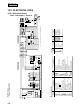
Suspension
bolt hole
Air outlet
(Indoor unit)
Suspension
bracket
B
Suspension
bracket
B
6505
50 50 Wall
275140
A
Suspension
bolt hole
Air outlet
(Indoor unit)
6505
8 8 Wall
275140
10.5.1 Installation of indoor unit
(1) Selection of installation location
(a) A place where good air circulation and delivery can be obtained.
(b) A place where ceiling has enough strength to support the unit.
(c) A place where there is no obstacle around the return air inlet
and supply air outlet ports.
(d) A place where there is no moist air or oil vapor which may
harm the heat exchanger.
(e) A place where the space shown below is secured.
(f) This unit uses a microcomputer as a control device. Therefore
avoid installing the unit near the equipment that generates strong
electromagnetic waves and noise.
NOTICE
All Wiring of this installation must comply with NATIONAL, STATE AND LOCAL REGULATIONS. These
instructions do not cover all variations for every kind of installation circumstance. Should further information be desired or
should particular problems occur, the matter should be referred to Mitsubishi Heavy Industries. Ltd.
through your local
distributor.
WARNING
BE SURE TO READ THESE INSTRUCTIONS CAREFULLY BEFORE BEGINNING INSTALLATION. FAILURE TO
FOLLOW THESE INSTRUCTIONS COULD CAUSE SERIOUS INJURY OR DEATH, EQUIPMENT MALFUNCTION
AND/OR PROPERTY DAMAGE.
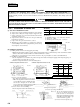
Model
Air reach
FDEN208H
7.5
FDEN258H
8
FDEN308H
9
FDEN408H,508H
9.5
Air reach
Unit: m
[Conditions]
(1) Installation height .... 2.4~3.0 m above the floor
(2) Fan speed .... High
(3) Air flow speed at reach point .... 0.5 m/sec
Ceiling mounting installation
Unit: mm
(2) Installation preparation
(a) Drilling of holes for interconnecting piping and wiring.
1) Drill a hole through the wall in accordance with the piping diameter. We recommend using a hole saw drill of 70~86mm
diameter and the hole should be drilled on an incline from inside to outside.
2) Insert the accessory piping sleeve into the hole and cut it to the proper length in accordance with wall thickness.
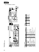
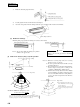
(b) Installation of suspension bolts.
1) Use the template sheet to determine the positions of suspension bolts and refrigerant pipings. The refrigerant piping can
be routed either to the right, left, top or rear.
2) Positions of suspension bolts are as in the drawing below.
¡When the suspension brackets face in
¡When the suspension brackets face out
Unit: mm
Item A B C
FDEN208H
FDEN258H
308H
408H
FDEN508H
1000
1260
1470
900
1160
1370
984
1244
1454
Unit: mm
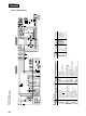
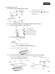
3) In case of wooden structures.
¡Use main strength members for suspension.
¡When the suspension beams have members
spaced 900 mm apart use small beams that
are at least 6 cm square, in case the beams
are spaced more than 180 mm apart use small
beams that are more than 90 mm square.
4) In case of ferro-concrete buildings.
Fix the suspension bolts in the following way.
5) Length of suspension.
(in case of exposed type installation)
(1) In case the suspension bracket is
set to face in, and the suspension
bolts are made to the length as
shown in the left drawing, the bolts
ends will be put in the plastics caps
of the indoor unit top panel.
(2) Do not remove the plastics caps.
Notes
100 or
more
150 or
more
5 or more
Obstacles
300
or
more
Holes for suspension bolts
Holes for suspension bolts
Clamps
Clamps
Ceiling board
Building
framework
Second floor member
House framework member
Suspension beams for
installation of air conditioner
Suspension beams for
installation of air conditioner
In case of wooden framework construction
In case of wooden framework (two storied building)
Insertion
150 ~ 160mm
Concrete
Steel reinforcement rods
M8 or M10 suspension bolts
Suspension bolts
Ceiling board
25 ~ 45 mm