
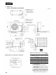
Specifications


420
FDEN-H
40
95
580
335
L
3
L2
L4
L1
260
150150
55 50 15
40
53
50
10
330
103 15
15 15
880
690
290
55
40
35 35
110
11050
195
195
150
7050
311
351
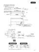
Liquid piping:ø6.35 (1/4")
(Flare connecting)
Gas piping:ø15.88 (5/8")
(Flare connecting)
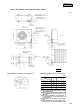
Liquid piping:ø6.35 (1/4")
(Flare connecting)
Gas piping:ø15.88 (5/8")
(Flare connecting)
Holes for anchor bolt
(M10 × 4 pcs.)
Holes for drain
(ø20 × 3 pcs.)
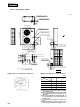
Air outlet
Air inlet
Air
inlet
( )
Maintenance
space
Opening for electric wiring
Opening for
electric wiring
Terminal block
40
50 15
5027
50
5015
40
A
Opening for piping
and electric wiring
Electric wiring
Opening for piping
and electric wiring
Opening for piping and
electric wiring
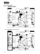
(3) Outdoor unit
Models, FDC208HEN3A, FDCP208HEN3A
Unit:mm
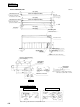
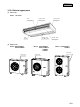
Minimum allowable space to the obstacles
Mark
123
L
1
Open Open 500
L
2
300 5 Open
L
3
100 150 100
L
4
555
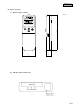
Installation
type
Notes (1) Avoid the location where four sides are entirely
surrounded by walls.
(2) Fix the unit by anchor bolts without fail.
Restrict the protrusion length of anchor bolt to
15 mm and under.
(3)
When strong wind blows against the unit, direct the
discharge port at a right angle to the wind direction.
(4)
Secure the space of 1 m and over at the top of unit.
(5) Make the height of obstruction wall in front of
discharge port lower than the height of unit.
Required space for maintenance and air flow
Unit: mm
VIEW A