Manual No. ’07 . SRK-T .
CONTENTS 1. GENERAL INFORMATION .............................................................................. 1 1.1 Specific features ....................................................................................... 1 1.2 How to read the model name ................................................................... 1 2. SELECTION DATA........................................................................................... 2.1 Specifications ..........................................................
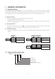
1 GENERAL INFORMATION 1.1 Specific features The “MITSUBISHI HEAVY INDUSTRIES, LTD.” room air-conditioner: SRK series are of split and wall mounted type and the unit consists of indoor unit and outdoor unit with refrigerant precharged in factory. The indoor unit is composed of room air cooling or heating equipment with operation control switch and the outdoor unit is composed of condensing unit with compressor.
2 SELECTION DATA 2.
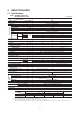
Model SRK28HG (Indoor unit) SRC28HG (Outdoor unit) (220/230/240V) Model SRK28HG Item (1) Refrigerant piping Operation data(1) Cooling capacity Heating capacity(1) Power source Cooling input Running current (Cooling) Heating input Running current (Heating) Inrush current COP Sound level Cooling Power level Noise level Sound level Heating Power level Exterior dimensions Height × Width × Depth Color Net weight Refrigerant equipment Compressor type & Q’ty Motor Starting method Heat exchanger Refrigerant
Model SRK40HG (Indoor unit) SRC40HG (Outdoor unit) (220/230/240V) Model SRK40HG Item Refrigerant piping Operation data(1) Cooling capacity(1) Heating capacity(1) Power source Cooling input Running current (Cooling) Heating input Running current (Heating) Inrush current COP Sound level Cooling Power level Noise level Sound level Heating Power level Exterior dimensions Height × Width × Depth Color Net weight Refrigerant equipment Compressor type & Q’ty Motor Starting method Heat exchanger Refrigerant c
2.2 Range of usage & limitations Models All models Item Indoor return air temperature (Upper, lower limits) Cooling operation : Approximately 21 to 32˚C Heating operation : Approximately 15 to 30˚C Outdoor air temperature (Upper, lower limits) Cooling operation : Approximately 21 to 43˚C Heating operation : Approximately - 5 to 21˚C Refrigerant line (one way) length Max. 15m Max. 5m (Outdoor unit is higher) Max.
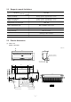
(2) Outdoor unit Drain holes (ø20) 50 12 111.4 99.4 290 312.5 350 43.1 313.1 23.5 Models All models 104.9 14 349.5 439.1 510 780 165.1 18.9 61.9 2-16×12 Terminal block Service valve (Liquid) Flare connection ø6.35 (1/4'') 33.5 540 138.4 42.5 95.9 14 40˚ 40˚ - Service valve (Gas) Flare connection 20, 28: ø9.52 (3/8'') 40: ø12.
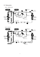
2.4 Piping system Models SRK20HG, 28HG Indoor unit Outdoor unit Flare connecting Piping (Gas) ø9.52 Cooling cycle Heating cycle Service valve (Gas) Outdoor air temp. sensor Check joint 4 way valve Accumulator Muffler Room temp. sensor Discharge temp. sensor Heat exchanger sensor Heat exchanger Heat exchanger Compressor Piping (Liquid) ø6.
2.5 Selection chart Correct the cooling and heating capacity in accordance with the conditions as follows. The net cooling and heating capacity can be obtained in the following way. Net capacity = Capacity shown on specification ✕ Correction factors as follows. (1) Coefficient of cooling and heating capacity in relation to temperatures Coefficient of cooling & Heating capacity in relation to temperature 1.3 1.2 Cooling 1.1 1.0 Heating 0.9 0.8 0.7 0.6 Outdoor air D.B. temperature ˚C D.B.
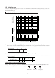
BR 1 FMI CFI Y/G ZNR BK WH J N CC L CM2 WH 52C WH CM BK U 3 CM1 CNW Printed circuit board - 5 9- SM G RD CNU WH 5 J F 250V 3.15A IC15 RD 3 RD BK 52C 2/N 1 RD N 52C-3 HEAT EXCHANGER 52C-4 BR WH BK Y/G 3 RD WH 2/N BK 1 Y F CNG 51C 52X1 CNM CNE BK ZNR 250V 3.15A CFO Y U 8 Color symbol Black BK Blue BL Brown BR Light blue LB RD Red WH White Y Yellow Y/G Yellow/Green 2 2 1 CNU D.
Outdoor unit Indoor unit TB Y/G RD 3 WH 2/N FMI CNU CFI Y/G RD J ZNR N CC L CM2 WH 52C U 3 WH CM CM1 BK CNW Printed circuit board - 5 10 - SM G RD RD 3 J F 250V 3.15A IC15 WH 5 BR 1 RD BK 52C Y/G 3 RD WH 2/N BK 1 BK N 52C-3 HEAT EXCHANGER 52C-4 BR WH BK 1 TB WH BR LB Y/G Model SRK40HG Power source 1 Phase 220/230/240V 50Hz 52X1 CNM CNE Y F CNG ZNR 250V 3.
4 OUTLINE OF OPERATION CONTROL BY MICROCOMPUTER 4.1 Operation control function by remote control switch Remote control Models All models ◆ Operation selection FAN SPEED button OPERATION MODE select button Each time the button is pushed, the indicator is switched over in turn. Each time the button pushed, the indicator is switched over in turn. ON/OFF (luminous) button HI POWER/ECONO button Press for starting operation, press again for stopping. This button changes the HIGH POWER/ ECONOMY mode.
Unit indication selection Models All models RUN light (green) Illuminates during operation and CLEAN operation. TIMER light (yellow) Illuminates during TIMER operation. HI POWER light (green) Illuminates during HIGH POWER operation. ECONO light (orange) Illuminates during ECONOMY operation. 4.2 Unit ON/OFF button When the remote control batteries become weak, or if the remote control is lost or malfunctioning, this button may be used to turn the unit on and off.
4.4 Custom cord switching procedure If two wireless remote controls are installed in one room, in order to prevent wrong operation Jumper wire (J6) due to mixed signals, please modify the printed circuit board in the indoor unit’s control box and the remote control using the following procedure. Be sure to modify both boards. If only one board is modified, receiving (and operation) cannot be done.
4.6 Timer operation (1) Comfortable timer setting (ON timer) If the timer is set at ON when the operation select switch is set at the cooling or heating, or the cooling or heating in auto mode operation is selected, the comfortable timer starts and determines the starting time of next operation based on the initial value of 15 minutes and the relationship between the room temperature at the setting time (temperature of room temperature sensor) and the setting temperature. (Max.
4.7 Outline of heating operation (1) Operation of major functional components Functional components Indoor fan motor Item When the compressor command is OFF When the compressor command is ON When the compressor goes OFF due to an anomalous stop.
(b) When the compressor and outdoor fan are stopped 1) While the compressor operation is delayed. 2) Up until 5 minutes have passed Speed 9 Speed 5 Speed 3 Speed 3 Auto fan control, or the set fan speed since the end of a compressor start delay operation, when 52C goes OFF, the indoor unit’s fan OFF speed changes forcibly from OFF to speed 1. 25 30 30 30 34 37 34 40 43 Indoor heat exchanger temp.
(c) Operation of functinal components during defrosting operation ON Compressor command OFF Hot keep Controlled by the indoor heat exchanger temperature Hot keep ON Indoor unit fan OFF The chart at left is for reference. Hot keep control governs operation during heating. Lit RUN light Flashes ON Outdoor unit fan OFF ON 110 sec. 4-way valve OFF Defrost start operation 120 sec. Defrost operation 120 sec. Operation after defrost is ended.
4.8 Outline of cooling operation (1) Operation of major functional components Functional components Indoor fan motor Item When the compressor command is OFF When the compressor command is ON When the compressor goes OFF due to an anomalous stop.
4.9 Outline of dehumidifying operation (1) Choose the appropriate operation block area by the difference between room temperature and thermostat setting temperature as shown below. ¡ Operation block area D block C block –2 Room temp. B block A block 0 +3 – Setting temp.(deg) (2) Start up operation C.D block A.
4.10 Outline of automatic operation (1) Determination of operation mode The unit checks the room temperature and the outdoor air temperature after operating the indoor and outdoor blowers for 20 seconds, determines the operation mode and the room temperature setting correction value, and then begins in the automatic operation. Cooling 27.5 25.5 Dehumidifying Room temperature (˚C) 19.
4.12 Protective control function (1) Frost prevention for indoor heat exchanger (During cooling or dehumidifying) (a) Operating conditions (i) Indoor heat exchanger temperature (detected with Th2) is lower than 2.5ºC. (ii) 3 minutes elapsed after the start of operation.
(6) Serial signal transmission error protection (a) Purpose: Prevents malfunction resulting from error on the indoor ↔ outdoor signals. (b) Detail of operation: When the indoor unit controller ↔ outdoor unit controller signals cannot be received, the compressor is stopped immediately. Simultaneously, the red LED on the printed circuit board of outdoor unit controller flashing 6 times for 0.5 second at intervals of 8 seconds. Once the operation stops, it does not start any more.
5 APPLICATION DATA SAFETY PRECAUTIONS ¡ Please read these “Safety Precautions” first then accurately execute the installation work. WARNING and CAUTION , those points ¡ Though the precautionary points indicated herein are divided under two headings, which are related to the strong possibility of an installation done in error resulting in death or serious injury are listed in the WARNING section.
5.1 Selection of location for installation (1) Indoor unit (a) (b) (c) (d) (e) (f) (g) (2) Where there is no obstructions to the air flow and where the cooled air can be evenly distributed. A solid place where the unit or the wall will not vibrate. A place where there will be enough space for servicing. (Where space mentioned right can be secured) Where wiring and the piping work will be easy to conduct.
5.2 Installation of indoor unit (1) Installation of installation board Fixing of installation board Look for the inside wall structures (Intersediate support or pillar and firaly install the unit after level surface has been checked.) 450 INSTALLATION SPACE (INDOOR UNIT) (FRONT VIEW) Unit : mm 65 39.3 43.2 Space 138 206.5 102.5 200 44.5 252.2 Mating mark for level surface 44.
(3) Preparation of indoor unit (a) Mounting of connecting wires 1) Remove the lid(R). 2) Remove the wiring clamp. 3) Connect the connecting wire securely to the terminal block. Use cables for interconnection wiring to avoid loosening of the wires. CENELEC code for cables. Required field cables. H05RNR4G1.
[Drain hose changing procedures] 1. Remove the drain hose. 2. Remove the drain cap. ¡Remove the drain hose, ¡Remove it with hand or making it rotate. pliers. 3. Insert the drain cap. 4. Connect the drain hose. ¡Insert the drain cap which was removed at ¡I n s e r t t h e d r a i n h o s e procedure “2” securely using a hexagonal securely, makingit rotate. wrench, etc.
5.3 Installation of outdoor unit (1) Installation of outdoor unit (a) Make sure that the unit is stable in installation. Fix the unit to stable base. (b) When installing the unit at a higher place or where it could be toppled by strong winds, secure the unit firmly with foundation bolts, wire, etc. (c) Perform wiring, making wire terminal numbers conform to terminal numbers of indoor nuit terminal block. (d) Connect using ground screw located near mark.
(3) Air purge (a) Tighten all flare nuts in the pipings both indoor and outside will so as not to cause leak. (b) Connect service valve, charge hose, manifold valve and vacuum pump as is illustrated below. (c) Open manifold valve handle Lo to its full width, and perform vacuum or evacuation. Continue the vacuum or evacuation operation for 15 minutes or more and check to see that the vacuum gauge reads – 0.1 MPa (– 76 cmHg).
5.5 Test run (1) Conduct trial run after confirming that there is no gas leaks. (2) When conducting trial run set the remote control thermostat to continuous operation position. However when the power source is cut off or when the unit’s operation switch is turned off or was turned to fan operation position, the unit will not go into operation in order to protect the compressor. (3) Explain to the customer on the correct usage of the air conditioner in simple layman’s terms.
6 MAINTENANCE DATA 6.1 Trouble shooting (1) Trouble shooting to be performed prior to exchanging PCB, (Printed circuit board) [Common to all models] All the models described in this chapter are controlled by a microcomputer. When providing maintenance service to customers it is necessary to understand the function controlled by a microcomputer thoroughly, so as not to mistakenly identify correct operations as mis-operations.
(2) Self diagnosis display on indoor unit TIMER light ON RUN light Outdoor unit LED Trouble Cause 1 time flash OFF Heat exchanger sensor error ¡ Broken heat exchanger sensor wire, connector poor connection 2 time flash OFF Room temperature sensor error ¡ Broken room temperature sensor wire, connector poor connection 6 time flash OFF Indoor fan motor error ¡ Defective fan motor, connector poor connection TIMER light RUN light keeps flashing RUN light ON OFF Outdoor air temperature senso
[Compressor faulty, compressor wiring disconnected.] Trouble of outdoor unit NO Overload operation? Short circuit, Check if the heat exchanger is dirty, stopped up, etc. YES NO Is the refrigerant level proper? Adjust the level to the proper level. YES NO Is the wiring to the compressor connected securely? Connect it securely. YES Check the compressor.
[Wiring error including power cable, defective indoor/ outdoor unit PCB] Error of signal transmission NO Does error persist after power reset? Trouble by transient cause, not unit trouble. YES NO Is there any wrong connection on indoor/outdoor unit wiring? Correct improper wire connection on indoor/ outdoor unit. YES Is DC 0~Approx. 12V detected between 2~3 terminals on indoor unit terminal block? NO Defective indoor unit PCB YES Is DC 0~Approx.
(5) Inspection procedures of indoor electrical equipment Is fuse (3.15A) blown? NO Replace fuse. YES Is voltage applied between terminals 1~2 on terminal block? (AC 220/230/240V) NO Replace PCB. YES Is DC 0~12V detected between terminals 2~3 on terminal block? NO Replace PCB. YES Indoor electrical equipment are normal. Notes (1) Since the communication timing signal is transmitted only when the 52C is turned ON, check it under the operating condition. (2) Check the voltage on the terminal block.
6.2 Servicing (1) Evacuation The evacuation is an procedure to purge impurities......noncondensable gas, air, moisture from the refrigerant equipment by using a vacuum pump. Since the refrigerant R22 is very insoluble in water, even a small amount of moisture left in the refrigerant equipment will freeze, causing what is called water clogging. ¡ Evacuation procedure (a) Check to ensure that there is no internal pressure in the unit.
WALL MOUNTED TYPE ROOM AIR-CONDITIONER Air-Conditioning & Refrigeration Systems Headquarters 16-5, 2-chome, Kounan, Minato-ku, Tokyo, 108-8215, Japan Fax : (03) 6716-5926 - 2- No.