
Instruction manual

INSTALLATION INSTRUCTIONS R−410A Ductless Split System: DLF4(A/H), DLC4(A/H)
8 421 01 9220 00
INSTALLATION GUIDE
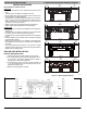
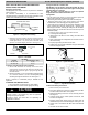
Ideal installation locations include:
Indoor Unit
S A location where there are no obstacles near inlet and outlet
area.
S A location which can bear the weight of indoor unit.
S Do not install indoor units near a direct source of heat such as
direct sunlight or a heating appliance.
S A location which provides appropriate clearances as outlined in
Figure 1.Be sure to leave enough Distance to allow access for
routine maintenance. The installation site should be 66 in.
(1676mm) or more above the floor.
S Select a place away from potential electronic interference.
S Select a place where the filter can be removed easily.
Outdoor Unit
S A location which is convenient to installation and not exposed to
strong wind.
S A location which can bear the weight of outdoor unit and where
the outdoor unit can be mounted in a level position.
S A location which provides appropriate clearances as outlined in
Figure1.
S Do not install the indoor or outdoor units in a location with special
environmental conditions.
S Make sure that the outdoor unit is installed in accordance with
the installation instructions,and is convenient for maintenance
and repair.
S See the refrigerant piping table for the maximum height
difference between indoor and outdoor units, and the maximum
length of the connecting tubing.
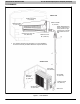
INDOOR UNIT INSTALLATION
INSTALL MOUNTING PLATE
1. Carefully remove the mounting plate from the unit box.
2. The mounting plate should be located horizontally and lev-
el on the wall. All minimum spacings shown in Figure 1
through Figure 3 should be maintained.
3. If the wall is block, brick, concrete or similar material, drill
.2” (5 mm) diameter holes and insert anchors for the ap-
propriate mounting screws.
4. Attach the mounting plate to the wall.
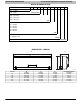
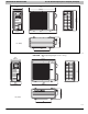
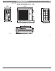
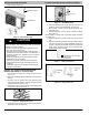
5.1
(129.5)
2
(50.8)
5.5
(139.7)
21.3
(541.0)
27
(685.8)
6.8
(172.7)
8
(203.2)
7.2
(182.9)
09&12K Unit
18K Unit
24K Unit
in. (mm)
27
(685.8)
29.4
(746.8)
13.7
(348.0)
10.0
(254.0)
30 & 36K Unit
A12378
Figure 2 - Mounting Plate Spacing
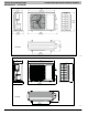
Level
6 in. 6 in.
See Hole
Size Tables
See Hole
Size Tables
Figure 3 - Install Mounting Plate