
Instruction manual
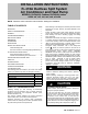

INSTALLATION INSTRUCTIONS R−410A Ductless Split System: DLF4(A/H), DLC4(A/H)
2 421 02 9220 00
GENERAL
These instructions cover the installation, start−up and servicing
of DLC4(A/H) outdoor and DLF4(A/H) indoor units ductless
systems.
SYSTEM REQUIREMENTS
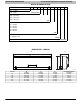
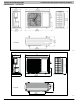
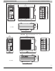
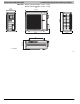
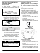
Allow sufficient space for airflow and servicing unit. See Figure. 1
for minimum required distances between unit and walls or
ceilings.
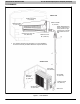
Piping
IMPORTANT: Both refrigerant lines must be insulated
separately.
S Minimum refrigerant line length between the indoor and outdoor
units is 10 ft. (3 m).
S The following maximum lengths are allowed:
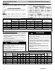
REFRIGERANT LINE LENGTHS ft. (m)
Unit Size
Max Line
Length
Max Elevation
(ID over OD)
Max Elevation
(OD over ID)
9K 50 (15) 33 (10) 33 (10)
12K 66 (20) 33 (10) 33 (10)
18, 24K 82 (25) 33 (10) 33 (10)
30, 36K 98 (30) 33 (10) 33 (10)
S The following are the piping sizes.
PIPE SIZES
Unit Size Mix Phase Vapor
9, 12K 1/4” 3/8”
18K 1/4” 1/2”
24, 30, 36K 1/4” 5/8”
R−410A Refrigerant Charge Table
Unit Size
Charge Amount *
LBS (kg)
Additional Charge Amount **
oz/ft (g/m)
Metering Device ***
Cool Only Heat Pump Cool Only Heat Pump
9K 2.65 (1.20) 2.65 (1.20) 0.16 (15) 0.22 (20) EXV
12K 2.86 (1.30) 2.86 (1.30) 0.16 (15) 0.22 (20) EXV
18K 3.09 (1.40) 3.09 (1.40) 0.16 (15) 0.22 (20) EXV
24K 3.53 (1.60) 3.53 (1.60) 0.16 (15) 0.54 (50) EXV
30K −−−− 5.30 (2.40) −−−− 0.54 (50) EXV
36K 5.30 (2.40) 5.73 (2.60) 0.54 (50) 0.54 (50) EXV
* Charge is for piping that runs up to 25 ft. (7.6 m)
** For piping runs greater than 25 ft. (7.6 m), add this amount of charge per foot of extra piping, up to the allowable length, specified in the above table.
*** EXV − Electronic Expansion Device
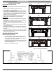
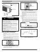
Connecting (Power and Control Cable)
S The main power is supplied to the outdoor unit. The field
supplied connecting cable from the outdoor unit to indoor unit
consists of four wires and provides the power for the indoor unit
as well as the communication signal and ground between the
outdoor and indoor unit.
Two wires are high voltage AC power, one is low voltage DC
signal and one is a ground wire.
S Consult local building codes, NEC (National Electrical Code) or
CEC (Canadian Electrical Code) for special requirements.
CAUTION
!
EQUIPMENT DAMAGE HAZARD
Failure to follow this caution may result in equipment
damage or improper operation.
S Based on the MCA’s in the electrical table, only 14 AWG
wire should be used.
S Use copper conductors only with a minimum 300 volt
rating and 2/64 inch thick insulation.
CAUTION
!
EQUIPMENT DAMAGE HAZARD
Failure to follow this caution may result in equipment
damage or improper operation.
S Be sure to comply with local codes while running wire from
indoor unit to outdoor unit.
S Every wire must be connected firmly. Loose wiring may
cause terminal to overheat or result in unit malfunction. A
fire hazard may also exist. Therefore, be sure all wiring is
tightly connected.
S No wire should be allowed to touch refrigerant tubing,
compressor or any moving parts.
S Disconnecting means must be provided and shall be
located within sight and readily accessible from the air
conditioner.
S Connecting cable with conduit shall be routed through
hole in the conduit panel.
Electrical Data Table
Unit
Size
System Voltage
Volts−Ph.−Freq.
Operating
Voltage
Compressor Outdoor Fan Indoor Fan
MCA
Max Fuse/
CB Amps
(MOCP)
RLA LRA FLA
Output
Watts Volts FLA HP
Output
Watts
(Min/Max)
9K 115−1−60 103/127 12.2 33.0 0.17 30 115 V−AC 0.38 0.056 20 16 25
12K 115−1−60 103/127 12.4 33.0 0.17 30 115 V−AC 0.38 0.056 20 16 25
12K 208/230−1−60 187/253 5.3 13.8 0.14 30 208/230 V−AC 0.20 0.056 20 10 15
18K 208/230−1−60 187/253 9.4 13.8 0.37 60 208/230 V−AC 0.21 0.075 20 16 20
24K 208/230−1−60 187/253 10.5 18.5 1.10 90 176−375 V−DC 0.24 0.068 60 16 20
30K 208/230−1−60 187/253 12.0 40.0 0.45 100 208/230 V−AC 0.40 0.106 40 15 25
36K 208/230−1−60 187/253 13.5 67.0 0.73 170 208/230 V−AC 0.47 0.114 60 17 30