
Instruction manual

INSTALLATION INSTRUCTIONS R−410A Ductless Split System: DLF4(A/H), DLC4(A/H)
14 421 01 9220 00
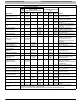
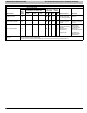
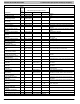
TROUBLESHOOTING
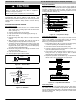
The unit has onboard diagnostics. Error codes will appear on the LED display on the front panel of the indoor unit in place of the
temperature display. Error codes are also displayed on the outdoor unit microprocessor board with colored LED lights. The tables
following explain the error codes for the specific models.
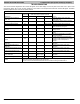
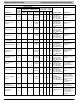
UNITS 9K & 12K, 115 Volts
Malfunction
Display on
Indoor Unit
State of the Lamps of Outdoor Unit PCB
Reasons
Error Code Green−LED2 Red−LED3 Yellow_LED4
Stop for anti−freeze protection of
indoor −unit
E2 Flash−4 Times Flash−3 Times
Refrigerant leakage. indoor unit air flow
blocked. Filter dirty.
Stop for discharge temp protection E4 Flash−7 Times
Low refrigerant. Capillary blocked. Ambient
temp is abnormal.
Stop for low voltage protection E5 Flash−5 Times Low voltage, ambient temp is abnormal.
Stop for communication malfunction E6 No Flash
Communication line failure, Main PCB failure.
Outside interference, wiring error.
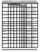
Stop for compressor overload
protection
H3 Flash−8 Times
Compressor overheat. Low refrigerant.
Capillary blocked.
Overload protection H4 Flash−6 Times
Ambient temp is abnormal. Heat exchanger
blocked.
Stop for IPM module protection H5 Flash−4 Times
IPM module over temperature, low voltage,
silica grease problem
DC motor (indoor unit) does not
operate
H6
DC motor control terminal contact problem,
fan does not rotate smoothly due to incorrect
installation, motor or control panel is
damaged.
Indoor ambient temperature sensor
malfunction
F1
Bad terminal connection. Temp sensor
malfunction.
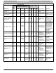
Indoor tube temperature sensor
malfunction
F2
Bad terminal connection. Temp sensor
malfunction.
Outdoor ambient temperature sensor
malfunction
F3 Flash−6 Times
Bad terminal connection. Temp sensor
malfunction.
Outdoor tube temperature sensor
malfunction
F4 Flash−5 Times
Bad terminal connection. Temp sensor
malfunction.
Outdoor discharge temperature
sensor malfunction
F5 Flash−7 Times
Bad terminal connection. Temp sensor
malfunction.
Automatic defrosting H1 Flash−2 Times H1 signal normal operation, heat pump only.
Remark
1. Error codes only can be seen in the type which has the temperature display PCB. Some types do not have
this function and have only the LED’s on the outdoor PCB.
2. If there is normal communication between the Indoor and Outdoor unit the green LED will be on.