
Instruction manual
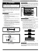

INSTALLATION INSTRUCTIONS R−410A Ductless Split System: DLF4(A/H), DLC4(A/H)
421 01 9220 00 13
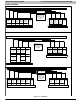
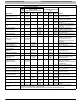
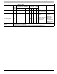
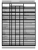
WIRING DIAGRAMS
DLC4/DLF4 9K − 12K, 115−1−60 Connection Diagram
Connecting Cable
Outdoor to Indoor
Use Copper
Conductors Only
With Minimum 300
Volt, 2/64” Thick
Insulation
N S L L N GND
Power to
Indoor
Unit
Control to
Indoor
Unit
Power to
Indoor
Unit
Main
Power
Supply
Main
Power
Supply
Ground
Power
from
Outdoor
Unit
Control
from
Outdoor
Unit
Power
from
Outdoor
Unit
Ground
N S L GND
DLC4 9K − 12K Outdoor Unit Terminal Block DLF4 9K − 12K Indoor Unit Terminal Block
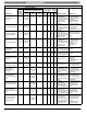
DLC4/DLF4 12K, 208/230−1−60 Connection Diagram
SL1 GND
Power to
Indoor
Unit
Control to
Indoor
Unit
Ground
Power
from
Outdoor
Unit
Control
from
Outdoor
Unit
Ground
DLC4 9K − 12K Outdoor Unit Terminal Block
DLF4 12K Indoor Unit Terminal Block
Use Copper
Conductors Only
With Minimum 300
Volt, 2/64” Thick
Insulation
Connecting Cable
Outdoor to Indoor
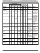
115−1−60 Low V DC
L1
L2
L2
GND
208/230−1−60 Low V DC 208/230−1−60
208/230−1−60 208/230−1−60
Power to
Indoor
Unit
Main Power
Supply
Main Power
Supply
SL1 GNDL2
Power
from
Outdoor
Unit
208/230−1−60 Low V DC 208/230−1−60
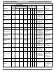
DLC4/DLF4 18K − 36K, 208/230−1−60 Connection Diagram
Connecting Cable
Outdoor to Indoor
Use Copper
Conductors Only
With Minimum 300
Volt, 2/64” Thick
Insulation
L2 S L1 L2 GND
Power to
Indoor
Unit
Control to
Indoor
Unit
Main
Power
Supply
Ground
Ground
L2 S L1 GND
DLC4 18K − 36K Outdoor Unit Terminal Block DLF4 18K − 36K Indoor Unit Terminal Block
115−1−60 115−1−60 115−1−60
115−1−60 Low V DC 115−1−60
208/230−1−60 Low V DC 208/230−1−60 208/230−1−60 208/230−1−60
Power to
Indoor
Unit
L1
Main
Power
Supply
Power to
Indoor
Unit
Control to
Indoor
Unit
Power to
Indoor
Unit
208/230−1−60 Low V DC 208/230−1−60
Figure 18 - Unit Wiring