
Instruction manual
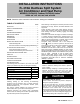

INSTALLATION INSTRUCTIONS R−410A Ductless Split System: DLF4(A/H), DLC4(A/H)
10 421 01 9220 00
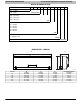
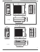
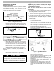
8. Reinstall field wiring cover.
Field Wiring Cover
Conduit Panel
A12411
Figure 8 - Install Outdoor Unit
CAUTION
!
EQUIPMENT DAMAGE HAZARD
Failure to follow this caution may result in equipment
damage or improper operation.
S Be sure to comply with local codes while running wire
from indoor unit to outdoor unit.
S Every wire must be connected firmly. Loose wiring may
cause terminal to overheat or result in unit malfunction. A
fire hazard may also exist. Therefore, be sure all wiring is
tightly connected.
S No wire should be allowed to touch refrigerant tubing,
compressor or any moving parts.
S Disconnecting means must be provided and shall be
located within sight and readily accessible from the air
conditioner.
S Connecting cable with conduit shall be routed through
hole in the conduit panel.
INSTALL ALL POWER, INTERCONNCECTING
WIRING, AND PIPING TO OUTDOOR UNIT
1. Run interconnecting piping and wiring from outdoor unit to
indoor unit.
2. Pass interconnecting cable through hole in wall (outside to
inside).
3. Lift indoor unit into position and route piping and drain
through hole in wall (inside to outside). Fit interconnecting
wiring into back side of indoor unit.
4. Hang indoor unit on upper hooks of wall mounting plate,
as shown in Figure 9 and Figure 12.
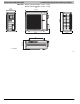
A08283
Figure 9 - Hanging Indoor Unit
5. Open front cover of indoor unit and remove field wiring ter-
minal block cover. See Figure 10.
Field Wiring
Cover
Interconnecting
Cable
A08279
Figure 10 - Field Wiring Cover
6. Pull interconnecting wire up from back of indoor unit and
position in close to the terminal block on indoor unit.
7. Push bottom of indoor unit onto mounting plate to com-
plete wall mount.
8. Connect wiring from outdoor unit per connection diagram.
See Figure 18.
NOTE: Polarity of power wires must match original connection
on outdoor unit.
9. Replace field wiring cover and close front cover of indoor
unit.
10. Connect refrigerant piping and drain line outside of indoor
unit. Refer to Figure 6 for proper installation of flare con-
nections. Complete pipe insulation at flare connection then
fasten piping and wiring to the wall as required. Com-
pletely seal the hole in the wall.
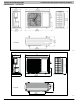
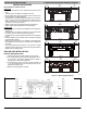
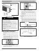
- Knockout 3 (o3o, o36 only)
Knockout 1
Knockout 2
A12410
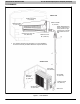
Figure 11 - Remove Knockouts
A12408
Figure 12 - Hang Indoor Unit