
Service manual

57
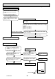
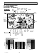
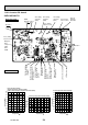
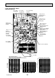
11-6. Test point diagram and voltage
11-6-1. Inverter P.C. board
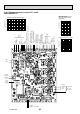
SUZ-KA25VA2.TH SUZ-KA35VA2.TH
-20 -10 0 10 20 30 40
0
10
20
30
40
50
60
70
80
90
100
Temperature(°C)
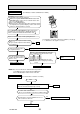
Defrost thermistor(RT61)
Ambient temperature thermistor(RT65)
Outdoor heat exchanger temperature thermistor(RT68)
Temperature(°C)
Discharge temperature thermistor(RT62)
0 1020304050607080
0
20
40
60
80
100
120
140
160
180
200
Temperature(°C)
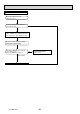
Fin temperature thermistor(RT64)
Resistance(kΩ)
Resistance(kΩ)
Resistance(kΩ)
Back side of unit
Fin temperature
thermistor /RT64
(CN642)
Ambient temperature
thermistor /RT65
(CN643)
Discharge temperature
thermistor /RT62
(CN641)
Defrost thermistor
/RT61(CN641)
LEV
connector
(CN724)
DB61
DC 260 - 300 V
Front side of unit
AC 230 V
Smoothing
capacitor
(C62)
Output to
drive
compressor
(LDU, LDV,
LDW)
(+)
(-)
Fuse (F701)
250 V 3.15 A
Smoothing
capacitor
(C61)
Smoothing
capacitor
(C63)
Fuse (F901)
250 V 3.15 A
R.V.coil
(CN721)
230 VAC
Jumper wire for
changing defrost
setting (JS)
Output to drive outdoor
fan motor (CN932)
Outdoor heat exchanger
temperature thermistor
/RT68 (CN644)
Fuse (F801)
250 V 3.15 A
0 102030405060708090100110120
0
100
200
300
400
500
600
700
AC 230 V
LED
monitor
lamp
OCH472A