
Service manual

28
SUZ-KA25VA2.TH SUZ-KA35VA2.TH SUZ-KA50VA2.TH
Refer to 11-5. "How to check in-
Refer to 11-5. "Check of LEV".
Refer to 11-5. "Check of outdoor
DC voltage DC voltage of inverter cannot be detected normally. Refer to 11-5. "How to check in-
Refer to 11-5. "How to check in-
Refer to 11-5. "Check of inverter
Refer to 11-5. "How to check in-
Refer to 11-5. "Check of outdoor
Refer to 11-5. "Check of LEV".
Refer to 11-5. "How to check in-
Refer to 11-5. "How to check mis-
Refer to 11-5. "Check of outdoor
Refer to 11-5. "How to check in-
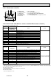
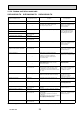
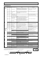
No. Symptom LED indication
Abnormal point/ Con-
dition
ecnednopserroCnoitidnoC
1
Outdoor unit
does not oper-
ate.
1-time flash every
2.5 seconds
Outdoor power sys-
tem
Overcurrent protection stop is continuously performed 3 times
within 1 minute after the compressor gets started, or failure of
restart of compressor has repeated 24 times.
Reconnect connector of compres-
sor.
verter/compressor".
Check stop valve.
•
•
•
2
Outdoor thermistors Discharge temperature thermistor, fin temperature thermistor,
defrost thermistor, P.C. board temperature thermistor or ambi-
ent temperature thermistor shorts or opens during compressor
running.
thermistors".
•
3
Outdoor control sys-
tem
Nonvolatile memory data cannot be read properly.
(The left lamp of OPERATION INDICATOR lamp of the indoor
unit lights up or fl ashes 7-time.)
Replace inverter P.C. board. •
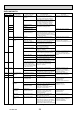
4
6-time flash
2.5 seconds OFF
Serial signal The communication fails between the indoor and outdoor unit
for 3 minutes. wiring and serial signal error.
•
5
11-time fl ash
2.5 seconds OFF
Stop valve/
Closed valve
Closed valve is detected by compressor current. Check stop valve. •
6
14-time flash
2.5 seconds OFF
Outdoor unit
(Other abnormality)
ehtfotrahcwolF".1.2-11otrefeR.evitcefedsitinuroodtuO
detailed outdoor unit failure mode
recall function".
•
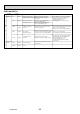
7
'Outdoor unit
stops and
restarts 3 min-
utes later' is
repeated.
2-time flash
2.5 seconds OFF
Overcurrent protec-
tion
Large current fl ows into intelligent power module, or compres-
sor repeats after 15 seconds when overcurrent protection oc-
curs within 10 seconds after compressor starts.
(Repeated 24 times at Maximum)
Reconnect connector of compres-
sor.
verter/compressor".
Check stop valve.
•
•
•
8
3-time flash
2.5 seconds OFF
Discharge tempera-
ture overheat protec-
tion
Temperature of discharge temperature thermistor exceeds
116°C, compressor stops. Compressor can restart if discharge
temperature thermistor reads 100°C or less 3 minutes later.
Check refrigerant circuit and refrig-
erant amount.
•
•
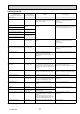
9
4-time flash
2.5 seconds OFF
Fin temperature/P.C.
board temperature
thermistor overheat
protection
Temperature of fin temperature thermistor on the heat sink
exceeds 75 ~ 80°C or temperature of P.C. board temperature
thermistor on the inverter P.C.board exceeds 70 ~ 75°C.
Check around outdoor unit.
Check outdoor unit air passage.
fan motor".
•
•
•
10
5-time flash
2.5 seconds OFF
High pressure protec-
tion
Indoor coil thermistor exceeds 70°C in HEAT mode. Defrost
thermistor exceeds 70°C in COOL mode.
Check refrigerant circuit and refrig-
erant amount.
Check stop valve.
•
•
11
8-time flash
2.5 seconds OFF
Compressor synchro-
nous abnormality
The waveform of compressor current is distorted. Reconnect connector of compres-
sor.
verter/compressor".
•
•
12
10-time flash
2.5 seconds OFF
Outdoor fan motor Outdoor fan has stopped 3 times in a row within 30 seconds
after outdoor fan start-up.
Refer to 11-5. "Check of outdoor
fan motor.
P.C. board.
•
•
13
12-time flash
2.5 seconds OFF
Each phase current
of compressor
Each phase current of compressor cannot be detected nor-
mally verter/compressor".
•
14
13-time flash
2.5 seconds OFF verter/compressor".
•
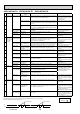
15
Outdoor unit
operates.
1-time flash
2.5 seconds OFF
Frequency drop by
current protection
Current from power outlet reaches the protection current, and
compressor frequency lowers.
The unit is normal, but check the
following.
Check if indoor fi lters are clogged.
Check if refrigerant is short.
Check if indoor/outdoor unit air cir-
culation is short cycled.
•
•
•
16
3-time flash
2.5 seconds OFF
Frequency drop by
high pressure protec-
tion
Temperature of indoor coil thermistor exceeds 55°C in HEAT
mode, compressor frequency lowers.
Frequency drop by
defrosting in COOL
mode
Indoor coil thermistor reads 8°C or less in COOL mode, com-
pressor frequency lowers.
17
4-time flash
2.5 seconds OFF
Frequency drop by
discharge tempera-
ture protection
Temperature of discharge temperature thermistor exceeds
111°C, compressor frequency lowers.
Check refrigerant circuit and refrig-
erant amount.
Refer to 11-5. "Check of LEV".
thermistors".
•
•
•
18
Outdoor unit
operates.
7-time flash
2.5 seconds OFF
Low discharge tem-
perature protection
Temperature of discharge temperature thermistor has been
50°C or less for 20 minutes. Check refrigerant circuit and refrig-
erant amount.
•
•
19
8-time flash
2.5 seconds OFF
PAM protection PAM:
Pulse Amplitude
Modulation
The overcurrent fl ows into IGBT (Insulated Gate Bipolar tran-
sistor : TR821) or when the bus-bar voltage reaches 320 V or
more, PAM stops and restarts.
This is not malfunction. PAM protec-
tion will be activated in the following
cases;
1 Instantaneous power voltage drop
(Short time power failure)
2 When the power supply voltage is
high.
20
9-time flash
2.5 seconds OFF
Inverter check mode The connector of compressor is disconnected, inverter check
mode starts.
Check if the connector of the com-
pressor is correctly connected.
verter/ compressor".
•
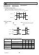
NOTE: 1. The location of LED is illustrated at the right fi gure. Refer to 11-6-1. or 11-6-2.
2. LED is lighted during normal operation.
The flashing frequency shows the number of times the LED blinks after every 2.5-second OFF.
(Example) When the fl ashing frequency is “2”.
ON
OFF
2.5-second OFF
2.5-second OFF
0.5-second ON
0.5-second ON
LED
Flashing →
Inverter P.C. board(Parts side)
11-3. Trouble shooting check table
OCH472A