
Service manual

25
Refer to 11-5. "How to check
Refer to 11-5. "How to check
Refer to 11-5. "Checkof LEV".
Refer to 11-5. "Check
Refer to 11-5. "Check
Refer to 11-5. "Check of LEV".
Refer to 11-5. "How to check
Refer to 11-5. "How to check
Refer to 11-5. "Check
Refer to 11-5. "How to check
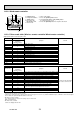
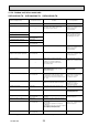
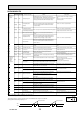
Abnormal point
(Failure mode/protection)
LED indication
(Outdoor P.C. board)
Condition
———)lamroN(enoN
Outdoor power system
—
Overcurrent protection stop is continuously
performed 3 times within 1 minute after
the compressor gets started.
Reconnect connectors.
inverter/compressor".
Check stop valve.
•
•
•
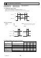
Discharge temperature thermistor 1-time flash every
2.5 seconds
Thermistor shorts or opens during compressor
running. of outdoor thermistors".
Defective outdoor thermistors
can be identified by checking
the blinking pattern of LED.
•
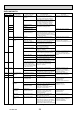
Defrost thermistor
Fin temperature thermistor 3-time flash
2.5 seconds OFF
P.C. board temperature thermistor 4-time flash
2.5 seconds OFF
Ambient temperature thermistor 2-time flash
2.5 seconds OFF
Overcurrent 11-time flash
2.5 seconds OFF
Large current fl
ows into intelligent power module.
Reconnect compressor connector.
inverter/compressor".
Check stop valve.
•
•
•
Compressor synchronous abnormality
(Compressor start-up failure protection)
12-time flash
2.5 seconds OFF
Waveform of compressor current is distorted.
Reconnect compressor connector.
inverter/compressor".
•
•
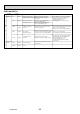
Discharge temperature
—
Temperature of discharge temperature
thermistor exceeds 116°C, compressor stops.
Compressor can restart if discharge
temperature thermistor reads 100°C or
less 3 minutes later.
Check refrigerant circuit and
refrigerant amount.
•
•
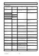
High pressure
—
Temperature indoor coil thermistor exceeds
70°C in HEAT mode.
Temperature defrost thermistor exceeds
70°C in COOL mode.
Check refrigerant circuit and
refrigerant amount.
Check stop valve.
•
•
Fin temperature/P.C. board temperature 7-time flash
2.5 seconds OFF
Temperature of fi n temperature thermistor on
the inverter P.C. board exceeds 75 ~ 80°C,
or temperature of P.C. board temperature
thermistor on the inverter P.C. board exceeds
70 ~ 75°C.
Check around outdoor unit.
Check outdoor unit air passage.
of outdoor fan motor".
•
•
•
Outdoor fan motor
—
Outdoor fan has stopped 3 times in a row
within 30 seconds after outdoor fan start-up.
Refer to 11-5. "Check
of outdoor fan motor".
of inverter P.C. board".
•
Nonvolatile memory data 5-time flash
2.5 seconds OFF
Nonvolatile memory data cannot be read
properly.
Replace the inverter P.C. board.•
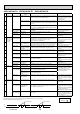
Discharge temperature
—
Temperature of discharge temperature
thermistor has been 50°C or less for 20 minutes.
Check refrigerant circuit
and refrigerant amount.
•
•
DC voltage 8-time flash
2.5 seconds OFF
DC voltage of inverter cannot be detected
normally. inverter/compressor".
•
Each phase current of compressor 9-time flash
2.5 seconds OFF
Each phase current of compressor cannot be
detected normally.
Overcurrent Compressor open-phase 10-time flash
2.5 seconds OFF
Large current fl ows into intelligent power
module (IPM).
The open-phase operation of compressor
is detected.
The interphase short out occurs in the output of
the intelligent power module (IPM).
The compressor winding shorts out.
Reconnect compressor connector.
inverter/compressor".
•
•
Stop valve (Closed valve) 14-time flash
2.5 seconds OFF
Closed valve is detected by compressor current. Check stop valve. •
NOTE: Blinking patterns of this mode differ from the ones of Troubleshooting check table (11-3.).
Correspondence
SUZ-KA25VA2.TH SUZ-KA35VA2.TH SUZ-KA50VA2.TH
11-2-4. Outdoor unit failure mode table
OCH472A