SPLIT-TYPE, HEAT PUMP AIR CONDITIONERS September 2011 No.OCH472 REVISED EDITION-A HFC utilized TECHNICAL & SERVICE MANUAL R410A R410A Outdoor unit [Model names] SUZ-KA25VA2 SUZ-KA35VA2 SUZ-KA50VA2 SUZ-KA60VA2 SUZ-KA71VA2 Revision: • Errors in "11. TROUBLESHOOTING" have been corrected in REVISED EDITION-A. [Service Ref.] SUZ-KA25VA2.TH SUZ-KA35VA2.TH SUZ-KA50VA2.TH SUZ-KA60VA2.TH SUZ-KA71VA2.TH • Some descriptions have been modified. • Please void OCH472.
1 COMBINATION OF INDOOR AND OUTDOOR UNITS 1-1. INDOOR UNIT SERVICE MANUAL Outdoor unit Heat pump type Indoor unit SUZService Ref. Service Manual No. KA25VA2.TH KA35VA2.TH KA50VA2.TH KA60VA2.TH KA71VA2.TH — SLZ-KA25VA(L).TH SLZ-KA35VA(L).TH OC320 — — Heat pump without electric heater SLZ-KA25VAQ.TH SLZ-KA35VAQ.TH OCH493 — — SEZ-KD25VA(L).TH — SEZ-KD35VA(L).TH HWE0711 — — — — — — — — — — — — — — — — — — — — — — — — SLZ-KA50VAQ.TH — — — SLZ-KA50VA(L).
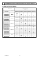
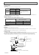
2 TECHNICAL CHANGES INFORMATION FOR THE AIR CONDITIONER WITH R410A REFRIGERANT oil Refrigerant Refrigerant • This room air conditioner adopts an HFC refrigerant (R410A) which never destroys the ozone layer. • Pay particular attention to the following points, though the basic installation procedure is same as that for R22 conditioners. 1 As R410A has working pressure approximate 1.6 times as high as that of R22, some special tools and piping parts/ materials are required. Refer to the table below.
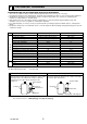
Conversion chart of refrigerant temperature and pressure (MPa [Gauge]) 4.0 Saturated liquid pressure 3.5 R410A 3.0 R22 2.5 2.0 NOTE: The unit of pressure has been changed to MPa on the international system of units (SI unit system). 1.5 1.0 The conversion factor is: 1 (MPa [Gauge]) =10.2 (kgf/cm2 [Gauge]) 0.5 0.0 -0.5 -30 -20 -10 0 10 20 30 40 50 60 ( ) 1. Tools dedicated for the air conditioner with R410A refrigerant The following tools are required for R410A refrigerant.
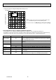
2. Refrigerant piping 1 Specifications Use the refrigerant pipes that meet the following specifications. Outside diameter mm 6.35 9.52 9.52 12.7 15.88 Pipe For liquid For gas Wall thickness mm 0.8 0.8 0.8 0.8 1.0 Insulation material Heat resisting foam plastic Specific gravity 0.045 Thickness 8 mm • Use a copper pipe or a copper-alloy seamless pipe with a thickness of 0.8 mm. Never use any pipe with a thickness less than 0.8mm, as the pressure resistance is insufficient.
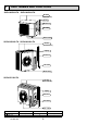
3 PART NAMES AND FUNCTIONS SUZ-KA25VA2.TH SUZ-KA35VA2.TH Air inlet (back and side) Piping Drain hose Air outlet Drain outlet SUZ-KA50VA2.TH SUZ-KA60VA2.TH Air inlet (back and side) Piping Drain hose Air outlet Drain outlet SUZ-KA71VA2.TH Air inlet (back and side) Piping Drain hose Air outlet Drain outlet Model Drain socket Drain cap OCH472A SUZ-KA25/35VA2.TH 1 - SUZ-KA50/60VA2.TH 1 2 6 SUZ-KA71VA2.
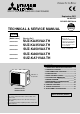
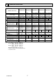
4 SPECIFICATION Outdoor Service Ref. Electrical Compressor data Fan motor SUZ-KA35VA2.TH SUZ-KA50VA2.TH SUZ-KA60VA2.TH Cooling Heating Single phase 230V, 50Hz 6.75 6.45 6.05 0.30 SNB130FGBH(T) 900 U-V 0.98 U-W 0.98 V-W 0.98 RC0J60-AA WHT-BLK 15.2 BLK-RED 15.2 RED-WHT 15.2 Cooling Heating Single phase 230V, 50Hz 9.75 8.05 9.45 0.30 SNB130FGBH(T) 900 U-V 0.98 U-W 0.98 V-W 0.98 RC0J60-AA WHT-BLK 15.2 BLK-RED 15.2 RED-WHT 15.2 SUZ-KA71VA2.TH Cooling Heating Single phase Power supply 230V, 50Hz 8.
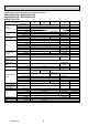
Specifications and rating conditions of main electric parts SUZ-KA25VA2.TH SUZ-KA35VA2.TH SUZ-KA50VA2.TH SUZ-KA60VA2.TH SUZ-KA71VA2.TH Item Current transformer Smoothing capacitor Diode module Fuse Inteligent power module Model SUZ-KA25VA2. SUZ0KA35VA2. SUZ-KA50VA2. SUZ-KA60VA2. SUZ-KA71VA2.
5 NOISE CRITERIA CURVES SUZ-KA35VA2.TH SUZ-KA25VA2.TH FAN SPEED FUNCTION 46 HEATING 46 FAN SPEED FUNCTION High Med. SPL(dB(A)) COOLING 47 HEATING 48 LINE Test conditions, Cooling : Dry-bulb temperature 35 Wet-bulb temperature (24 ) Heating : Dry-bulb temperature 7 Wet-bulb temperature 6 90 Test conditions, Cooling : Dry-bulb temperature 35 Wet-bulb temperature (24 ) Heating : Dry-bulb temperature 7 Wet-bulb temperature 6 90 OCTAVE BAND SOUND PRESSURE LEVEL, dB re 0.
6 OUTLINES AND DIMENSIONS SUZ-KA25VA2.TH SUZ-KA35VA2.TH Unit: mm REQUIRED SPACE Basically open 100mm or more without any obstruction in front and on both sides of the unit. Bolt pitch for installation 304~325 44 Air in 40 2-Oval holes 10×21 Open two sides of left, right, or rear side. Air out 22.3 ore or m mm 0 0 2 17.5 Service panel 23 Liquid refrigerant pipe joint Refrigerant pipe (flared) :6.35 Handle 35 69 302.5 Gas refrigerant pipe joint Refrigerant pipe (flared) :9.52 99.5 10 164.
SUZ-KA50VA2.TH SUZ-KA60VA2.
SUZ-KA71VA2.TH Unit: mm Open as a rule 500mm or more if the front and both sides are open REQUIRED SPACE 417.5 Drain hole 40 50 Bolt pitch for installation 360 42 Air in 100mm or more 200mm or more if there are obstacles to both sides 100 mm or m ore Air out 2-Oval holes 10 21 350 500 175 840 Open as a rule 500mm or more if the back, both sides and top are open 81 109 mm or m ore Service panel Liquid refrigerant pipe joint Refrigerant pipe (flared) Ø 9.52 880 35 164.5 99.
NOTES:1. About the indoor side electric wiring, refer to the indoor unit electric wiring diagram for servicing. 2. Use copper conductors only. (For field wiring) 3. Symbols below indicate. : Terminal block 7 WIRING DIAGRAM SUZ-KA25VA2.TH SUZ-KA35VA2.
3~ MC U BLK WHT RED 1 3 SYMBOL CT C61,62,63 DB61,DB65 DSA F61 F701,F801,F901 HC930,IPM IC802 L61 L62 W MS V RED LDW LDV LDU U V P N IPM W R825 TR821 1 R61 14 3 MF MS 3~ CN932 5 3 5 F901 F801 R937A 1 T801 1 RT64 2 1 CN642 HC930 R937B IC802 RT68 CN644 RT65 RT61 RT62 CN641 4 1 LEV M 6 CN724 6 CT LD61 U F701 LD63 BRN U 1 CN721 LD-E1 2 F61 LD62 U LD-S L62 DSA PTC65 PTC64 X64 X63 21S4 BRN BLU RED GRN/YLW BLK S1 S3 S2 TB2 L N TB1 230V~ 1
SYMBOL CB1~3 CT1, 2 CT61 F64 F801 F911 HC930 HPS IPM L NAME SMOOTHING CAPACITOR CURRENT TRANSFORMER CURRENT TRANSFORMER FUSE (T2AL 250V) FUSE (T3.15AL 250V) FUSE (T1AL 250V) INTELLIGENT POWER MODULE HIGH PRESSURE SWITCH INTELLIGENT POWER MODULE REACTOR SYMBOL LEV MC MF NF NR64 PFC RS1~4 RT61 RT62 RT64 NAME EXPANSION VALVE COMPRESSOR FAN MOTOR NOISE FILTER VARISTOR POWER FACTOR CONTROLLER RESISTOR DEFROST THERMISTOR DISCHARGE TEMP. THERMISTOR FIN TEMP.
SUZ-KA71VA2.
8 REFRIGERANT SYSTEM DIAGRAM SUZ-KA25VA2.TH Unit: mm Refrigerant pipe ø9.52 (with heat insulator) 4-way valve Muffler Stop valve (with service port) Discharge temperature thermistor RT62 Flared connection Outdoor heat exchanger Muffler Outdoor heat exchanger temperature thermistor RT68 Ambient temperature thermistor RT65 Compressor Defrost thermistor RT61 Flared connection Refrigerant pipe ø6.35 (with heat insulator) Strainer #100 LEV Capillary tube ø3.0×ø2.0×240 R.V.
SUZ-KA50VA2.TH Unit: mm Muffler 4-way valve #100 Refrigerant pipe ø12.7 (with heat insulator) Stop valve (with service port) Flared connection Discharge temperature thermistor RT62 Defrost thermistor RT61 Outdoor heat exchanger Ambient temperature thermistor RT65 Compressor Outdoor heat exchanger temperature thermistor RT68 Flared connection LEV Receiver Refrigerant pipe ø6.35 (with heat insulator) Stop valve (with strainer) Strainer #100 R.V. coil heating ON cooling OFF Capillary tube ø3.6×ø2.
SUZ-KA71VA2.TH Unit: mm Refrigerant pipe ø15.88 (with heat insulator) Muffler 4-way valve #100 Stop valve (with service port) Flared connection Discharge temperature thermistor RT62 Defrost thermistor RT61 Outdoor heat exchanger Ambient temperature thermistor RT65 Compressor Outdoor heat exchanger temperature thermistor RT68 Flared connection LEV Strainer #100 Stop valve Refrigerant pipe ø9.52 (with heat insulator) OCH472A Capillary tube ø4.0×ø2.4×100 19 Strainer #100 R.V.
SUZ-KA25VA2.TH SUZ-KA60VA2.TH SUZ-KA35VA2.TH SUZ-KA71VA2.TH SUZ-KA50VA2.TH MAX. REFRIGERANT PIPING LENGTH Refrigerant piping: m Max. Height difference B Max. Length A Models SUZ-KA25VA2.TH SUZ-KA35VA2.TH SUZ-KA50VA2.TH SUZ-KA60VA2.TH SUZ-KA71VA2.TH 20 12 Gas Piping size O.D: mm Liquid 9.52 6.35 12.7 30 30(15) 15.88 9.52 ( ): MFZ-KA50VA-E4 MAX. HEIGHT DIFFERENCE Indoor unit + Max. Height difference B Max.
9 ACTUATOR CONTROL SUZ-KA25VA2.TH SUZ-KA60VA2.TH SUZ-KA35VA2.TH SUZ-KA71VA2.TH SUZ-KA50VA2.TH 9-1. Outdoor fan motor control The fan motor turns ON/OFF, interlocking with the compressor. [ON] The fan motor turns ON 5 seconds before the compressor starts up. [OFF] The fan motor turns OFF 15 seconds after the compressor has stopped running. 5 seconds 15 seconds ON Compressor OFF ON Outdoor fan OFF 9-2. R.V. coil control Heating . . . . . . . . . . . . . . . . . ON Cooling . . . . . . . . . . . . . .
10 SERVICE FUNCTIONS SUZ-KA25VA2.TH SUZ-KA35VA2.TH CHANGE IN DEFROST SETTING When the JS wire of the outdoor Inverter P.C. board is cut/ soldered, the defrost finish temperature is changed. (Refer to 11-6-1) Jumper wire JS 11 soldered (Initial setting) none (cut) Defrost finish temperature SUZ-KA25VA2.TH SUZ-KA35VA2.TH 5: 10: 8: 13: TROUBLESHOOTING SUZ-KA25VA2.TH SUZ-KA50VA2.TH SUZ-KA35VA2.TH SUZ-KA60VA2.TH SUZ-KA71VA2.TH 11-1. Cautions on troubleshooting 1.
11-2. Failure mode recall function As this air conditioner has a function to memorize all the failures that had happened, the latest failure detail can be recalled by following the procedures below. Use this function when the check code is not displayed with wired remote controller or the remote controller at use is wireless type. 11-2-1.
11-2-2. Wired remote controller °C °C SIMPLE TEMP. MENU BACK PAR-21MAA MONITOR/SET ON/OFF ON/OFF Turn on the power. Press the [CHECK] button twice. Set refrigerant address with [TEMP] button if system control is used. Press the [ON/OFF] button to stop the self-check. FILTER DAY CLOCK CHECK button Refrigerant address TEMP. button IC: Indoor unit OC: Outdoor unit Check code CHECK TEST OPERATION CLEAR 11-2-3.
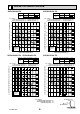
11-2-4. Outdoor unit failure mode table SUZ-KA25VA2.TH SUZ-KA35VA2.TH Abnormal point (Failure mode/protection) None (Normal) LED indication (Outdoor P.C. board) Condition Correspondence — — — Outdoor power system — Discharge temperature thermistor SUZ-KA50VA2.TH 1-time flash every 2.5 seconds Overcurrent protection stop is continuously performed 3 times within 1 minute after the compressor gets started. • Reconnect connectors. • Refer to 11-5. "How to check inverter/compressor".
SUZ-KA60VA2.TH Abnormal point Outdoor LED indication (Failure mode) LED1 LED2 Outdoor thermistors Lighting Once Details of abnormal Discharge temperature thermistor Defrost thermistor Twice Ambient temperature thermistor 3 times 4 times Fin temperature thermistor P.C.
SUZ-KA71VA2.TH Abnormal point (Failure mode / protection) None (Normal) LED indication (Outdoor P.C. board) Condition Correspondence — — — Outdoor power system — Discharge temperature thermistor 1-time flash every 2.5 seconds Defrost thermistor Fin temperature thermistor 3-time flash 2.5 seconds OFF P.C. board temperature thermistor 4-time flash 2.5 seconds OFF Ambient temperature thermistor 2-time flash 2.
11-3. Trouble shooting check table SUZ-KA25VA2.TH SUZ-KA35VA2.TH SUZ-KA50VA2.TH point/ ConNo. Symptom LED indication Abnormal Condition Correspondence dition Outdoor unit 1-time flash every Outdoor power sys- Overcurrent protection stop is continuously performed 3 times • Reconnect connector of compresdoes not oper- 2.5 seconds tem within 1 minute after the compressor gets started, or failure of sor. 1 ate. restart of compressor has repeated 24 times. • Refer to 11-5. "How to check inverter/compressor".
SUZ-KA60VA2.TH No. Symptom Indication LED1 (Red) LED2 (Yellow) Condition Abnormal point/Condition Outdoor unit does not operate. Lightning Twice Outdoor power system When IPM protection stop or lock protection stop is continuously performed three times within 1 minute after the compressor gets started, or when converter protection stop or bus-bar voltage protection stop is continuously performed three times within 3 minutes after start-up.
SUZ-KA60VA2.TH No. 20 Symptom Outdoor unit operates. 21 Indication LED1 (Red) LED2 (Yellow) Once Lighting Twice Lighting Condition Abnormal point/Condition Primary current protection When the input current exceeds 15A. Secondary current protection When the current of the compressor exceeds 15A. High-pressure protection When the indoor gas pipe temperature exceeds 45 during heating. Defrosting in cooling When the indoor gas pipe temperature falls 3 or below during cooling.
SUZ-KA71VA2.TH No. 1 Symptom Outdoor unit does not operate. Abnormal point/ Condition 1-time flash every Outdoor power sys2.5 seconds tem LED indication 3 6-time flash 2.5 seconds OFF 11-time flash 2.5 seconds OFF 14-time flash 2.5 seconds OFF 5 6 7 8 Outdoor control sys- Nonvolatile memory data cannot be read properly. tem (The upper lamp of OPERATION INDICATOR lamp of the indoor unit lights up or flashes 7-time.
11-4. Trouble criterion of main parts (1) SUZ-KA25VA2.TH SUZ-KA35VA2.TH Part name Check method and criterion Figure Defrost thermistor (RT61) Fin temperature thermistor (RT64) Measure the resistance using a tester. Ambient temperature thermistor (RT65) Refer to 11-6. “Test point diagram and voltage”, 11-6-1. “Inverter P.C. board”, for the chart of thermistor. Outdoor heat exchanger temperature thermistor(RT68) Discharge temperature thermistor (RT62) Measure the resistance using a tester.
11-4. Trouble criterion of main parts (2) SUZ-KA50VA2.TH SUZ-KA60VA2.TH SUZ-KA71VA2.TH Part name Check method and criterion Defrost thermistor (RT61) Fin temperature thermistor (RT64) Ambient temperature thermistor (RT65) Outdoor heat exchanger temperature thermistor (RT68) Measure the resistance using a tester. Discharge temperature thermistor (RT62) Measure the resistance using a tester. Before measurement, hold the thermistor with your hands to warm it up. Figure Refer to 11-6.
[SUZ-KA25/35/50VA2.TH] 11-5. Troubleshooting flow A How to check inverter/compressor Disconnect the connector between compressor and the intelligent power module (IPM). See B “Check of open phase”. Check the voltage between terminals. Are the voltages balanced? Yes No Replace the inverter P.C. board. See D “Check of compressor”. Check the compressor.
[SUZ-KA25/35/50VA2.TH] D Check of compressor winding Disconnect the connector between the compressor and intelligent power module, and measure the resistance between the compressor terminals. <> at 3 points BLK-WHT Measure the resistance between the lead wires at 3 points. BLK-RED WHT-RED <> Refer to 11-4. 0 [Ω] ················Abnormal [short] Infinite [Ω] ·······Abnormal [open] NOTE: Be sure to zero the ohmmeter before measurement.
[SUZ-KA25/35/50VA2.TH] G Check of R.V. coil First of all, measure the resistance of R.V. coil to check if the coil is defective. Refer to 11-4. In case CN721 is not connected or R.V. coil is open, voltage is generated between the terminal pins of the connector although any signal is not being transmitted to R.V. coil. Check if CN721 is connected. Unit operates COOL mode even if it is set to HEAT mode. Disconnect connector between the compressor and the intelligent power module.
[SUZ-KA25/35/50VA2.TH] 280 - 370 VDC I Check of power supply DB61 Disconnect the connector (CN61) between compressor and intelligent power module. Turn ON power supply and press EMERGENCY OPERATION switch. Does the left lamp of OPERATION INDICATOR lamp on the indoor unit light up? Yes Is there voltage 280 - 370 VDC between DB61 (+) and DB61 (–) on the inverter P.C. board? (Refer to 11-6-1. or 11-6-2.) No Rectify indoor/outdoor connecting wire.
[SUZ-KA25/35/50VA2.TH] J Check of LEV (For wired remote controller use model) Start Turn on power supply to the outdoor unit after checking LEV coil is fixed to the LEV body securely. Yes Normal Is "click - click" sound heard? Or, do you feel vibration of the LEV coil with a hand? No Disconnect the connector CN724 is there normal resistance to LEV coil? Yes Replace the inverter P.C. board. No Replace the LEV coil. K Check of inverter P.C. board Check the outdoor fan motor. (Refer to H.
[SUZ-KA25/35/50VA2.TH] L How to check miswiring and serial signal error (For wireless remote controller use model) Turn OFF the power supply. Is there rated voltage in the power supply? Yes Check the power supply. No Turn ON the power supply. Is there rated voltage between outdoor terminal block S1 and S2? Yes No Check the wiring. Press EMERGENCY OPERATION switch once.
[SUZ-KA25/35/50VA2.TH] L How to check miswiring and serial signal error (For wired remote controller use model) Turn OFF the power supply. Is there rated voltage in the power supply? Yes Check the power supply. No Turn ON the power supply. Is there rated voltage between outdoor terminal block S1 and S2? Yes No Check the wiring. Press TEST button once.
[SUZ-KA25/35/50/60VA2.TH] M Electromagnetic noise enters into TV sets or radios Is the unit earthed? Yes Is the distance between the antennas and the indoor unit within 3 m, or is the distance between the antennas and the outdoor unit within 3 m? No Earth the unit. No Yes Extend the distance between the antennas and the indoor unit, and/or the antennas and the outdoor unit.
[SUZ-KA60VA2.TH] Outdoor unit does not operate. (LED display: display OFF) N Check of power supply Start Check the connecting of parts of main power supply circuit. Turn on power supply. Is there voltage of 230V AC in the power supply terminal block? No Check the power supply cable. Yes Is the output voltage from the noise filter P.C. board 230V AC? No Is fuse (F64) blown? No Yes Yes Is the input voltage to the power board 230V AC? Replace the fuse. No Replace the reactor.
[SUZ-KA60VA2.TH] When unit cannot operate neither by the remote controller nor by EMERGENCY OPERATION switch. Indoor unit does not operate. Outdoor unit does not operate. O How to check miswiring and serial signal error (when outdoor unit does not work) (For wireless remote controller use model) As for indoor unit. Turn OFF the power supply. Is there rated voltage in the power supply? No Check the power supply. Yes Turn ON the power supply.
[SUZ-KA60VA2.TH] When unit cannot operate neither by the remote controller. Indoor unit does not operate. Outdoor unit does not operate. O How to check miswiring and serial signal error (when outdoor unit does not work) (For wired remote controller use model) As for indoor unit. Turn OFF the power supply. No Is there rated voltage in the power supply? Check the power supply. Yes Turn ON the power supply. Is there rated voltage between outdoor terminal block S1 and S2? No Check the wiring.
[SUZ-KA60VA2.TH] The cooling operation or heating operation does not operate. (LED display: Both LED1 and LED2 lighting) P Check of R.V. coil • When heating operation does not work. 1. Disconnect the lead wire leading to the compressor. 2. 3 minutes after turning on the power supply, start EMERGENCY OPERATION in HEAT mode. Is there voltage of 230V AC between pin1 and pin 2 at connector CN912? 1.
[SUZ-KA60VA2.TH] When cooling, heat exchanger of non-operating indoor unit frosts. When heating, non-operating indoor unit get warm. LED display: Q Check of LEV LED1 Lighting 6 time LED2 Lighting Goes out Turn on power supply to the outdoor unit after checking LEV coil is mounted to the LEV body securely. Yes Is "click - click" sound heard? Or, do you feel vibration of the LEV coil with a hand? Normal No Yes Disconnect the connector CN795.
[SUZ-KA60VA2.TH] When thermistor is abnormal. S Check of outdoor thermistors Disconnect the connector in the outdoor electronic control P.C. board or the outdoor power board Yes (see below table), and measure the resistance of thermistor. Is the thermistor normal? Replace the thermistor. No Reconnect the connector CN661 on the outdoor electronic control P.C. board and CN3 on the power board, and disconnect the lead wire leading to the compressor.
[SUZ-KA60VA2.TH] When the operation frequency does not go up from lowest frequency. U Check of HPS 1. Disconnect the connector CN681 in the electronic control P.C. board. 2. Check the resistance of HPS after 1 minutes have passed since the outdoor unit power supply was turned off. Infinity Check the resistance between each terminal. Replace HPS. 0 Reconnect CN681. Turn on power supply to the indoor and outdoor unit. 3 minutes later, starts EMERGENCY OPERATION.
[SUZ-KA71VA2.TH] a How to check inverter/compressor Disconnect the connector between compressor and the intelligent power module (IPM). See 11-5. Check the voltage between terminals. Are the voltages balanced? Yes No “Check of open phase”. Replace the inverter P.C. board. See 11-5. D “Check of compressor”. Check the compressor.
[SUZ-KA71VA2.TH] d Check of compressor winding ●Disconnect the connector between the compressor and intelligent power module, and measure the resistance between the compressor terminals. <> at 3 points BLK-WHT Measure the resistance between the lead wires at 3 points. BLK-RED WHT-RED <> Refer to 11-4. 0 [Ω] ················Abnormal [short] Infinite [Ω] ·······Abnormal [open] NOTE: Be sure to zero the ohmmeter before measurement.
[SUZ-KA71VA2.TH] g Check of outdoor thermistors Disconnect the connector of thermistor in the outdoor P.C. board (see below table), and measure the resistance of thermistor. Is the resistance of thermistor normal? (Refer to 11-6-3.) Yes No Replace the thermistor except RT64. When RT64 is abnormal, replace the inverter P.C. board. Reconnect the connector of thermistor. Turn ON the power supply and press EMERGENCY OPERATION switch.
[SUZ-KA71VA2.TH] i Check of outdoor fan motor Disconnect the connectors CN931 and CN932 from the inverter P.C. board. Check the connection between the connector CN931 and CN932. Is the resistance between each terminal of outdoor fan motor normal? (Refer to 11-4.) No Yes Disconnect CN932 from the inverter P.C. board, and turn on the power supply. Rotate the outdoor fan motor manually and measure the voltage of CN931.
[SUZ-KA71VA2.TH] k Check of LEV (For wireless remote controller use model) Turn ON the power supply. While pressing both OPERATION SELECT button and TOO COOL button on the remote controller at the same time, press RESET button. First, release RESET button. And release the other two buttons after all LCD except the set temperature in operation display section of the remote controller is displayed after 3 seconds.
[SUZ-KA71VA2.TH] l Check of inverter P.C. board Check the outdoor fan motor. (Refer to 11-5.i.) Is the fuse (F901) blown on the inverter P.C. board? Yes No Check the connection of the connectors (CN931, CN932) of the outdoor fan motor. If the connection is poor, make it correct. Operate the outdoor unit by starting EMERGENCY OPERATION. Check the LED indication on the inverter P.C. board. Does the LED flash 10 times? Yes (10-time flash) No Check the corresponding parts following LED indication.
[SUZ-KA71VA2.TH] m How to check miswiring and serial signal error Turn OFF the power supply. Is there rated voltage in the power supply? Yes Check the power supply. No Turn ON the power supply. Is there rated voltage between outdoor terminal block S1 and S2? Yes No Check the wiring. Press EMERGENCY OPERATION switch once.
[SUZ-KA71VA2.TH] n Electromagnetic noise enters into TV sets or radios Is the unit earthed? Yes Is the distance between the antennas and the indoor unit within 3 m, or is the distance between the antennas and the outdoor unit within 3 m? No Earth the unit. No Yes Extend the distance between the antennas and the indoor unit, and/or the antennas and the outdoor unit.
11-6. Test point diagram and voltage 11-6-1. Inverter P.C. board SUZ-KA25VA2.TH SUZ-KA35VA2.TH Smoothing capacitor (C63) DB61 DC 260 - 300 V (-) (+) Back side of unit Smoothing capacitor (C62) Smoothing capacitor (C61) Fuse (F701) 250 V 3.15 A Fuse (F801) 250 V 3.15 A AC 230 V R.V.coil (CN721) 230 VAC Fuse (F901) 250 V 3.
11-6-2. Inverter P.C. board SUZ-KA50VA2.TH Back side of unit Smoothing capacitor (C63) DB61 DC 260 ~300 V (-) (+) Smoothing capacitor (C62) Smoothing capacitor Fuse (F701) (C61) 250 V 3.15 A R.V.coil (CN721) 230 VAC Fuse (F801) 250 V 3.15 A AC 230 V Fuse (F901) 250 V 3.
11-6-3. Inverter P.C. board SUZ-KA71VA2.TH Fuse (F62) T2.0AL250V Fuse (F601) T3.15AL250V R.V.
11-6-4. Outdoor electronic control P.C. board SUZ-KA60VA2.
11-6-5. Noise filter P.C. board SUZ-KA60VA2.TH CN901 To electronic CN902 CN903 control To power To power P.C. board board board { { 230V AC 50Hz Input { { CN912 R.V.
11-6-6. Outdoor power board SUZ-KA60VA2.TH Connect to the compressor Voltage among phases: 5V to 180V 325-370V DC Output (Red) (+) 1 Connect to the earth CN2 Connect to the controller board (+)1-5(–): Signal transmission (To electronic control P.C. board) 5V DC pulse wave (+)2-5(–): Zero cross signal 3-4 : Not used (+)6-5(–): 15V (+)7-5(–): 15V (–) 3 (White) CN3 Fin temperature thermistor RT64 reception (From ) Signal electronic control P.C.
12 DISASSEMBLY INSTRUCTIONS <"Terminal with locking mechanism" Detaching points> The terminal which has the locking mechanism can be detached as shown below. There are two types ( Refer to (1) and (2)) of the terminal with locking mechanism. The terminal without locking mechanism can be detached by pulling it out. Check the shape of the terminal before detaching. (1) Slide the sleeve and check if there is a locking lever or not. Sleeve Locking lever SUZ-KA25VA2.
OPERATING PROCEDURE PHOTOS 2. Removing the inverter assembly, inverter P.C. board Photo 3 (1) Remove the cabinet and panels. (Refer to 1.) (2) Disconnect the lead wire to the reactor and the following connectors: CN721 (R.V. coil) CN932 (Fan motor) CN641 (Defrost thermistor and discharge temperature thermistor) CN643 (Ambient temperature thermistor) CN644 (Outdoor heat exchanger temperature thermistor) CN724 (LEV) (3) Remove the compressor connector (CN61).
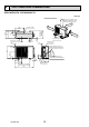
OPERATING PROCEDURE PHOTOS 5. Removing outdoor fan motor Photo 6 (1) Remove the cabinet and panels. (Refer to 1.) (2) Disconnect the following connectors: CN932 (Fan motor) (3) Remove the propeller nut. (Photo 7) (4) Remove the propeller. (Photo 7) (5) Remove the screws fixing the fan motor. (Photo 7) (6) Remove the fan motor. Outdoor heat exchanger temperature thermistor 6. Removing the compressor and 4-way valve (1) Remove the cabinet and panels. (Refer to 1.
SUZ-KA50VA2.TH SUZ-KA60VA2.TH NOTE: Turn OFF power supply before disassembling. OPERATING PROCEDURE PHOTOS 1. Removing the cabinet Photo 1 (1) Remove the screws of the service panel. (2) Remove the screws of the top panel. (3) Remove the screw of the valve cover. (4) Remove the service panel. (5) Remove the top panel. (6) Remove the valve cover. (7) Remove the screws of the cabinet. (8) Remove the cabinet. (9) Remove the screws of the back panel. (10) Remove the back panel.
OPERATING PROCEDURE PHOTOS 2. Removing the inverter assembly, inverter P.C. board and power board (for SUZ-KA50VA2.TH) (1) Remove the top panel, cabinet, service panel and back panel. (Refer to 1.) (2) Disconnect the lead wire to the reactor and the following connectors; CN721 (R.V.
OPERATING PROCEDURE PHOTOS 4. Removing the defrost thermistor, discharge temperature thermistor, outdoor heat exchanger temperature thermistor and ambient temperature thermistor Photo 7 Discharge temperature thermistor (1) Remove the top panel, cabinet and service panel. (Refer to 1.) (2) Remove the back panel. (Refer to 1.) (3) Remove the inverter assembly. (Refer to 2.) (4) Pull out the defrost thermistor from its holder. (Photo 8) (5) Pull out the discharge temperature thermistor from its holder.
OPERATING PROCEDURE PHOTOS 6. Removing the compressor and 4-way valve Photo 10 (1) Remove the top panel, cabinet and service panel. (Refer to 1.) (2) Remove the back panel. (Refer to 1.) (3) Remove the inverter assembly. (Refer to 2.) (4) Recover gas from the refrigerant circuit. NOTE: Recover gas from the pipes until the pressure gauge shows 0 kg/cm2 (0 MPa). (5) Detach the welded part of the suction and the discharge pipe connected with compressor. (Photo 11) (6) Remove the compressor nuts.
SUZ-KA71VA2.TH NOTE: Turn OFF power supply before disassembling. OPERATING PROCEDURE PHOTOS 1. Removing the cabinet Photo 1 (1) (2) (3) (4) (5) (6) (7) Remove the screws of the service panel. Remove the screws of the top panel. Remove the screw of the valve cover. Remove the service panel. Remove the top panel. Remove the valve cover. Disconnect the power supply and indoor/outdoor connecting wire. (8) Remove the screws of the cabinet. (9) Remove the cabinet. (10) Remove the screws of the back panel.
OPERATING PROCEDURE PHOTOS 2. Removing the inverter assembly, inverter P.C. board (1) Remove the cabinet and panels. (Refer to 1.) (2) Disconnect the lead wire to the reactor and the following connectors: CN602 (R.V. coil) CN931, CN932 (Fan motor) CN671 (Defrost thermistor, discharge temperature thermistor and outdoor heat exchanger temperature thermistor) CN672 (Ambient temperature thermistor) CN724 (LEV) (3) Remove the compressor connector.
OPERATING PROCEDURE PHOTOS 4. Removing the discharge temperature thermistor, defrost thermistor, outdoor heat exchanger temperature thermistor and ambient temperature thermistor (1) Remove the cabinet and panels. (Refer to 1.) (2) Disconnect the lead wire to the reactor and the following connectors:
OCH472A 73
HEAD OFFICE: TOKYO BLDG., 2-7-3, MARUNOUCHI, CHIYODA-KU, TOKYO100-8310, JAPAN cCopyright 2010 MITSUBISHI ELECTRIC ENGINEERING CO.,LTD Distributed in Sep. 2011 No.OCH472 REVISED EDITION-A Distributed in May. 2010 No.OCH472 PDF 4 Made in Japan New publication, effective Sep.