
Instruction Manual

1 2 3 4 5 6 7 8 9 10 45 46 47 48
a-Gr1 a-Gr2
b-Gr1
c-Gr1
c-Gr16
a-Gr16
SC-SL2N-E SC-SL2N-E SC-SL2N-E
abc
123 45678910
(∗3)(∗3)(∗3)(∗3)(∗2)
11 12
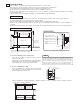
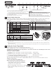
L1 L2/N COM DO1 DO2 COM DI1 DI2 DI3 A B
Super Link signal wire
Use the supplied
terminal (small).
(∗1)
J1
J2
J3
SW1 to 10
(Left-OFF, Right-ON)
1
2
3
4
5
6
7
8
9
10
Use the
supplied
terminal
(large).
Power supply
AC100 - 240V
50/60Hz
Operation output
(01)
Error output
(02)
Demand input
(I1)
Emergency stop input
(I2)
External timer input
(I3)
(∗1) Switching is needed if the connection is previous Super Link.
Actual type of network connection (New or previous Super Link) depends on the models of indoor units and outdoor units, etc. Please contact the agency or the
Sales representative.
(∗2) When J1 is disconnected, the Center/Remote does not be set from this central control. Please disconnect if multiple central controls are installed and another
main central control exists.
When J1 is disconnected, data is sent for the blower only during demand input (nothing is performed when SW6 is off) and for stop only during emergency stop input.
NOTE
Do not connect the power supply wire to another terminal.
Making the wrong connection can result in damage or burning of
electrical parts and is extremely dangerous.
Please check the wires again before turning on the power supply.
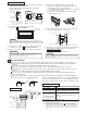
System Wiring
(1) Switch
ON
ON
OFF
ON
ON
ON
OFF
OFF
OFF
OFF
1
2
3
4
5
6
7
8
9
10
5 Control Switch Selection
6 Setting the Control Target Units
It is possible to change the setting as follows by settings of the PCB switches SW1 to SW10, J1, J2, and J3 on the central control.
Please change the control on site as necessary. It is recommended to change the setting by using a precise driver.
Make the settings for the units to be controlled by the central control.
For the setting procedure, see the user’s manual attached to the central contrl.
At shipping, none of the units are set as target units for control, and so the units to be controlled by this central control
must be set as control target units.
Three types of settings are available.
① Units are selected as control targets for central control and controlled
as a group
② Units are selected as control targets for central control but not grouped
③ Units are not selected as control targets for central control
(or units will be controlled by another central control)
Be sure to set the current time. This is needed for the program settings and error history display.
Turn on the power and press the three buttons (MENU, RESET, GROUP No. 10) at once more than five minutes, that can
initialize the setting contents.
SW No.
SW
(2) Jumper wires
J1
J2
J3
Power failure compensation function selector
ON
ON
OFF
OFF
ON
OFF
ON
OFF
Sending of program settings when power comes back on
(The operation status before the power failure is sent if
there is no program when power comes back on.)
Sending of operation status before power failure
(Do not make this setting.)
No data is sent when power comes back on
SW-1 SW-2 Function
Function
When disconnected
Short circuit (default)
Description
ON OFF
Default
Group control when using multiple units
This central control can control up to 64 target units
(up to 48 units when using the previous Super Link
setting). Multiple central controls must be installed to
control 65 or more air conditioner units.
When connecting multiple central controls on a single
network, any group settings can be made for each
central control.
Group setting
Individual setting
Not target units for control
(∗1)
Please connect to ground for signal wire and power supply wire.
(∗2)
The selected relay obtained at the site should have the following specifications: rated voltage
of DC 12V and maximum power consumption of DC 0.9W or less (80mA or less)
(∗3)
The selected relay obtained at the site should have the following specifications: Non-voltage "a"
contact input and capable of withstanding a minimum applied load of DC 12V and 10mA or less.
The DO and DI terminals are polar.
Do not connect three or more wires to the same terminal.
See table
at right
Auto mode can be set
Display
New
Center & Blower
Time Month.Day
See table
at right
Auto mode cannot be set
No display
Previous
Center
Month.Day Time
(Keep at Off)
(Keep at Off)
(Keep at Off)
Error history display
Sending of data during demand input
New/Prev. Super Link(∗1)
Filter sign display on/off
Automatic mode display
Power failure compensation
function
Setting not possible
(Including during external input.)
Setting
possible
(Do not disconnect.)
(Do not disconnect.)
Center/Remote setting (∗2)
(Including the allowed/prohibited settings of each remote control function)