
Hardware manual


21 LS Industrial Systems
2-347
Chap.2
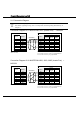
Connection Diagram 21-3: MASTER-K (Interface Module RS232C Port)
-
MICRO/I
PLC(RS-232C) HG1F/2F/2S/3F/4F(RS-232C)
Pin No.
Pin No.
Name
Name
HG1F
Connector
HG2F/
3F/4F
HG2S
1 CD FG 1 1 1
2 RXD SD 2 2 30
3 TXD RD 3 3 32
4 DTR RS 9 4 34
5 SG CS 6 5 36
6 DSR NC -
6
-
7 RTS SG 7 7 29
8 CTS NC - 8 -
9 RI ER - 20 -
D-sub, 9P connector socket type (HG1F)
D-sub, 25P connector socket type (HG2F/3F/4F)
D-sub, 37P connector plug type (HG2S)
D-sub, 25P connector socket type
Shield Wire
Connection Diagram 21-4
:
MASTER-K (Interface Module RS-485 Port )
-
MICRO/I
PLC(RS-485/422) HG1F/2F/2S/3F/4F(RS-485/422)
Pin No.
Pin No. Name
Name
HG1F
Connector
HG1F
Terminal
HG2F/
3F/4F
HG2S
- FG FG Cover - 1 1
- RDA TERM - - 9 -
- RDB RDA(RD+) 2 3 10 32
- SDA RDB(RD-) 7 4 16 33
- SDB SDA(SD+) 1 1 11 30
- SG SDB(SD-) 6 2 15 31
CS- 9 - 18 37
RS- 8 - 19 35
CS+ 4 - 21 36
RS+ 3 - 22 34
SG 5 5 7 29
D-sub, 9P connector socket type (HG1F)
D-sub, 25P connector socket type (HG2F/3F/4F)
D-sub, 37P connector plug type (HG2S)
Terminal Block
Internal
terminati
on
resistor
330-Ohm
Shield Wire
- There is no pin No. corresponding to TERM on the HG1F/HG2S. When inserting a
termination resistor, use a communication switch. For the setting of the switch, refer to "3
Important Points Regarding Wiring" in Chapter 1.