
Hardware manual


Chapter2 Connection to a PLC
2-336
20.3 Connection Diagram
The connector types given in the Connection Diagrams are for the unit and not the cable.
For details regarding wiring, refer to "3 Important Points Regarding About Wiring" in
Chapter 1.
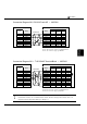
Connection Diagram 20-1: RS-485 D-sub 15P
-
MICRO/I
PLC(RS-485/422) HG1F/2F/2S/3F/4F(RS-485/422)
Pin No.
Pin No. Name
Name
HG1F
Connector
HG1F
Terminal
HG2F/
3F/4F
HG2S
1 FG FG Cover - 1 1
2 RXA TERM - - 9 -
3 TXA RDA(RD+) 2 3 10 32
4 CTSA RDB(RD-) 7 4 16 33
5 RTSA SDA(SD+) 1 1 11 30
7 SG SDB(SD-) 6 2 15 31
10 RXB CS- 9 - 18 37
11 TXB RS- 8 - 19 35
12 CTSB CS+ 4 - 21 36
13 RTSB RS+ 3 - 22 34
SG 5 5 7 29
D-sub, 9P connector socket type (HG1F)
D-sub, 25P connector socket type (HG2F/3F/4F)
D-sub, 37P connector plug type (HG2S)
D-sub, 15P connector socket type
Internal
terminati
on
resistor
330-Ohm
Shield Wire
- There is no pin No. corresponding to TERM on the HG1F/HG2S. When inserting a
termination resistor, use a communication switch. For the setting of the switch, refer to "3
Important Points Regarding Wiring" in Chapter 1.