
Hardware manual


19 FUJI
2-321
Chap.2
19.3 Connection Diagram
The connector types given in the Connection Diagrams are for the unit and not the cable.
For details regarding wiring, refer to "3 Important Points Regarding About Wiring" in
Chapter 1.
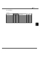
Connection Diagram 19-1:FLEX-PC series(Loader Port) - MICRO/I
PLC(RS-485/422) HG1F/2F/2S/3F/4F(RS-485/422)
Pin No.
Pin No.
Name
Name
HG1F
Connector
HG1F
Terminal
HG2F/
3F/4F
HG2S
- - FG Cover - 1 1
3 SDA TERM - - 9 -
4 SDB RDA(RD+) 2 3 10 32
5 RDA RDB(RD-) 7 4 16 33
6 RDB SDA(SD+) 1 1 11 30
8 SG SDB(SD-) 6 2 15 31
CS- 9 - 18 37
RS- 8 - 19 35
CS+ 4 - 21 36
RS+ 3 - 22 34
SG 5 5 7 29
Internal
termination
resistor
330-Ohm
D-sub, 9P connector socket type (HG1F)
D-sub, 25P connector socket type (HG2F/3F/4F)
D-sub, 37P connector plug type (HG2S)
Modular jack 8 Pin
Shield Wire
Connector Pin Layout for PLC side Modular jack
18
- There is no pin No. corresponding to TERM on the HG1F/HG2S. When inserting a
termination resistor, use a communication switch. For the setting of the switch, refer to "3
Important Points Regarding Wiring" in Chapter 1.
Connection Diagram 19-2: FLEX-PC series(Loader Port) + NN-CONV1 -
MICRO/I