
Hardware manual


Chapter2 Connection to a PLC
2-234
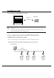
12.3 Connection Diagram
For details regarding wiring and termination resistors, refer to "3 Important Points
Regarding About Wiring" in Chapter 1.
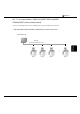
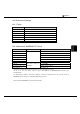
Connection Diagram 12-1: TWDNAC232D to MICRO/I
PLC(RS-232C) HG1F/2F/2S/3F/4F(RS-232C)
Pin No.
Pin No.
Name
Name
HG1F
Connector
HG2F/
3F/4F
HG2S
1 RS FG 1 1 1
2 ER SD 2 2 30
3 SD RD 3 3 32
4 RD RS 9 4 34
5 DR CS 6 5 36
6 SG NC - 6 -
7 SG SG 7 7 29
8 +5V NC - 8 -
Cover Shield ER - 20 -
D-sub, 9P connector socket type (HG1F)
D-sub, 25P connector socket type (HG2F/3F/4F)
D-sub, 37P connector plug type (HG2S)
Mini DIN8P
Shield Wire
In case of HG2F/3F/4Fa connection cable is available (part number: HG9Z-3C125).
The connection diagram 12-1 is not same as HG9Z-3C125. But both diagrams are available.
Refer to the Hardware Manual about the connection diagram of HG9Z-3C125.