
Hardware manual


Chapter2 Connection to a PLC
2-222
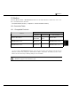
・ Word Device
Device Symbol
Device Name
HG PLC
Address Range
Read
/Write
Address
Gradual
Discrete Inputs WI %I 1 - 12273 R Dec
Discrete Outputs WQ %Q 1 - 12273 R/W Dec
Internal Coils WM %M 1 - 12273 R/W Dec
Temporary Coils WT %T 1 - 241 R/W Dec
Discrete Globals WG %G 1 - 7665 R/W Dec
System Status
References S
WS %S 1 - 113 R Dec
System Status
References SA
WSA %SA 1 - 113 R/W Dec
System Status
References SB
WSB %SB 1 - 113 R/W Dec
System Status
References SC
WSC %SC 1 - 113 R/W Dec
Register Memory R %R 1 - 16384 R/W Dec
Analog Inputs AI %AI 1 - 8192 R/W Dec
Analog Outputs AQ %AQ 1 - 8192 R/W Dec
The device ranges may differ depending on the PLC model. Please refer to PLC Manual for
supported memory ranges of the PLC you are using.