
Hardware manual


11 GE Fanuc Automation
2-217
Chap.2
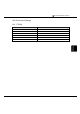
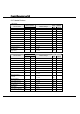
Connection Diagram 11-3: PLC(RS-485) to MICRO/I
PLC(RS-485/422) HG1F/2F/2S/3F/4F(RS-485/422)
Pin No.
Pin No.
Name
Name
HG1F
Connector
HG1F
Terminal
HG2F/
3F/4F
HG2S
1 Shield FG Cover - 1 1
9 RD(TRM) TERM - - 9 -
13 SD(B) RDA(RD+) 2 3 10 32
12 SD(A) RDB(RD-) 7 4 16 33
11 RD(B) SDA(SD+) 1 1 11 30
10 RD(A) SDB(SD-) 6 2 15 31
6 RTS(A) CS- 9 - 18 37
15 CTS(A) RS- 8 - 19 35
14 RTS(B) CS+ 4 - 21 36
8 CTS(B) RS+ 3 - 22 34
7 SG SG 5 5 7 29
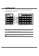
Internal
termination
resistor
330-Ohm
D-sub, 9P connector socket type (HG1F)
D-sub, 25P connector socket type (HG2F/3F/4F)
D-sub, 37P connector plug type (HG2S)
D-sub, 15P connector socket type
Shield Wire
- There is no pin No. corresponding to TERM on the HG1F/HG2S. When inserting a
termination resistor, use a communication switch. For the setting of the switch, refer to "3
Important Points Regarding Wiring" in Chapter 1.
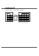
When you use the Terminal Block type of HG1F, make sure to configure the Hardware Flow
control to NONE because the HG1F doesn’t have control lines.