
Hardware manual


11 GE Fanuc Automation
2-215
Chap.2
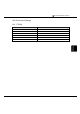
11.3 Connection Diagram
The connector types given in the Connection Diagrams are for the unit and not for the cable.
For details regarding wiring, refer to "3 Important Points Regarding Wiring" in Chapter 1.
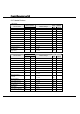
Connection Diagram 11-1: Series 90-30 Communication Coprocessor Module
(CMM) (RS-232C) to MICRO/I
PLC(RS-232C) HG1F/2F/2S/3F/4F(RS-232C)
Pin No.
Pin No.
Name
Name
HG1F
Connector
HG2F/
3F/4F
HG2S
1 Shield FG 1 1 1
2 TD SD 2 2 30
3 RD RD 3 3 32
4 RTS RS 9 4 34
5 CTS CS 6 5 36
8 DCD NC -
6
-
7 SG SG 7 7 29
20 DTR NC - 8 -
ER - 20 -
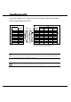
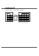
D-sub, 9P connector socket type (HG1F)
D-sub, 25P connector socket type (HG2F/3F/4F)
D-sub, 37P connector plug type (HG2S)
D-sub, 25P connector socket type
(unit side)
Shield Wire