
Hardware manual


11 GE Fanuc Automation
2-213
Chap.2
11 GE Fanuc Automation
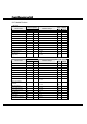
11.1 Connection Table
11.1.1 Compatible PLCs
WindO/I-NV2 Setting Name
Manufacturer
Series
Name
System
(CPU unit)
Link Unit
Interface
Flow
Control
Host I/F
Driver
RS-232C
(Connection
Diagram 11-1)
CPU331,CPU341,
CPU350,CPU351,
CPU352,CPU360,
CPU363,CPU364,
CPU374
IC693CMM311
RS-485 (422)-4
(Connection
Diagram 11-2)
Series90-30
CPU311,CPU313,
CPU323,CPU331
,
CPU341,CPU350,
CPU351,CPU352,
CPU360,CPU363,
CPU364,CPU374
Not required
(connects to
CPU(Power
Supply) unit
directly)
RS-485 (422)-4
(Connection
Diagram 11-3)
Nano
Micro
(14point)
RS-232C
(Connection
Diagram 11-4)
RS-232C
(Connection
Diagram 11-4)
GE Fanuc Automation
VersaMax
Micro
(23,28
point)
Not required
(connects to
CPU unit
directly)
RS-485 (422)-4
(Connection
Diagram 11-3)
Hardware
Series 90
(SNP-X)
* We tested with the PLC of underline part.