
Hardware manual


Chapter2 Connection to a PLC
2-200
9.3 Connection Diagram
The connector types given in the Connection Diagrams are for the unit and not the cable.
For details regarding wiring, refer to "3 Important Points Regarding About Wiring" in
Chapter 1.
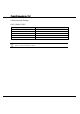
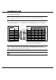
Connection Diagram 9-1: TOYOPUC-PC3J,PC3JD (Built-in Link) - MICRO/I
PLC(RS-485/422) HG1F/2F/2S/3F/4F(RS-485/422)
Pin No.
Pin No.
Name
Name
HG1F
Connector
HG1F
Terminal
HG2F/
3F/4F
HG2S
G FG Cover - 1 1
L(+) TERM - - 9 -
L(-) RDA(RD+) 2 3 10 32
0V RDB(RD-) 7 4 16 33
SDA(SD+) 1 1 11 30
SDB(SD-) 6 2 15 31
CS- 9 - 18 37
RS- 8 - 19 35
CS+ 4 - 21 36
RS+ 3 - 22 34
SG 5 5 7 29
Internal
termination
resistor
330-Ohm
D-sub, 9P connector socket type (HG1F)
D-sub, 25P connector socket type (HG2F/3F/4F)
D-sub, 37P connector plug type (HG2S)
Screw Terminal
Double Shield
- There is no pin No. corresponding to TERM on the HG1F/HG2S. When inserting a
termination resistor, use a communication switch. For the setting of the switch, refer to "3
Important Points Regarding Wiring" in Chapter 1.
When you use the Terminal Block type of HG1F, make sure to configure the Hardware Flow
control to NONE because the HG1F doesn’t have control lines.