
Hardware manual


Chapter2 Connection to a PLC
2-166
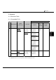
6.3 Connection Diagram
The connector types given in the Connection Diagrams are for the unit and not the cable.
For details regarding wiring, refer to "3 Important Points Regarding About Wiring" in
Chapter 1.
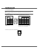
Connection Diagram 6-1: KV-700/1000, Conventional KV to MICRO/I
PLC(RS-232C) HG1F/2F/2S/3F/4F(RS-232C)
Pin No.
Pin No.
Name
Name
HG1F
Connector
HG2F/
3F/4F
HG2S
1 FG 1 1 1
2 SD 2 2 30
3 RD RD 3 3 32
4 SG RS 9 4 34
5 SD CS 6 5 36
6 NC -
6
-
SG 7 7 29
NC - 8 -
ER - 20 -
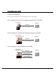
D-sub, 9P connector socket type (HG1F)
D-sub, 25P connector socket type (HG2F/3F/4F)
D-sub, 37P connector plug type (HG2S)
Modular connector
Shield Wire
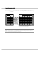
Connector Pin Layout for PLC side Modular jack
123456