
Hardware manual


Chapter2 Connection to a PLC
2-138
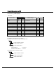
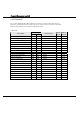
・ Word Device
Device Symbol
Device Name
HG PLC
Address Range
Read
/Write
Address
Gradual
Input WI I 0 - 277(*1) R 8
Output WO O 0 - 277(*1) R/W 8
Bit WB B 3000 - 99999 (*2) R/W 10
Timer (current value) TA T 3000 - 99999 (*2) R 10
Counter
(current value)
CA C
3000 - 99999 (*2)
R 10
Timer (preset value) TP T 3000 - 99999 (*2) R/W 10
Counter
(preset value)
CP C
3000 - 99999 (*2)
R/W 10
Integer N N 3000 - 99999(*2)(*3) R/W 10
BCD D D 3000 - 99999 (*2) R/W 10
ASCII A A 3000 - 99999 (*2) R/W 10
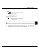
(*1) Address selection rule is as follows.
Standard device address format of WindO/I-NV2
I 277
Example
PLC-5 Address --- I
:277
WindO/I-NV2 Address --- I 277
2 di
g
its Rack number
1 di
g
its Grou
p
number
Allen-Bradley device address format
I 277
1 di
g
its Grou
p
number
2 di
g
its Rack number