
Hardware manual


4 Allen-Bradley PLCs
2-135
Chap.2
(*2) Address selection rule is as follows.
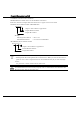
Standard device address format of WindO/I-NV2
N
255255
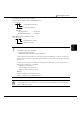
Example
SLC 500 Address --- N 255
:255
WindO/I-NV2 Address --- N 255255
3di
g
its Element number
3di
g
its File number
Allen-Bradley device address format
N
255
:
255
3di
g
its Element number
3di
g
its File number
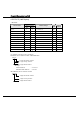
The input and output addresses are made up of the slot number and the word number.
- The address makeup is as follows:
Bottom digit: Word number
2nd and 3rd digits from the bottom: Slot number
- If the module in the slot has 16 or fewer points, the word number is 0, and if it is a 32-point
module, the word number is 0 for the lower word (bit 0 to bit 15) and 1 for the upper word (bit
16 to bit 31).
- In the case of a rack-type controller, the slot number is attributed as is, and in the case of a
package-type controller, it is as follows.
Package-type controller: 0
Left slot of the expansion rack: 1
Right slot of the expansion rack: 2
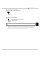
Example:
Address specification with SLC 500: I: 1.0
Address specification with WindO/I-NV2: 1
0
- You cannot directly write to inputs and outputs.
- A communication error will occur if you specify a file or element that is not allocated to the
SLC 500 data table map.