
Hardware manual


Chapter2 Connection to a PLC
2-110
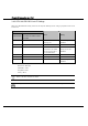
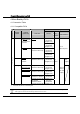
4 Allen-Bradley PLCs
4.1 Connection Table
4.1.1 Compatible PLCs
WindO/I-NV2 Setting Name
Manufacturer
Series
Name
System
(CPU unit)
Link unit
Interface
Flow
Control
Host I/F Driver
RS-232C
(Connection
Diagram 4-2)
All PLC-5
models that can
be connected to
1770-KF2
1770-KF2
RS-485 (422)-4
(Connection
Diagram 4-3)
RS-232C
(Connection
Diagram4-2)
PLC-5
All PLC-5
models
Not required
(connects to CPU unit)
RS-485 (422)-4
(Connection
Diagram 4-4)
PLC-5
(Half Duplex)
SLC 500 SLC5/03
SLC5/04
SLC5/05
Not required
(connects to CPU unit)
RS-232C
(Connection
Diagram 4-1)
SLC500
(Half
Duplex)
MicroLogix1000
MicroLogix1200
Not required
(connects to CPU unit)
RS-232C
(Connection
Diagram 4-5)
MicroLogix1100
Not required
(connects to CPU unit)
RS-232C
(Connection
Diagram 4-8)
Not required
(connects to Mini Din
connector on CPU unit)
RS-232C
(Connection
Diagram 4-5)
Allen-Bradley
MicroLogix
MicroLogix1500
Not required
(connects to D-sub
connector on CPU unit)
RS-232C
(Connection
Diagram 4-6)
ER
control
MicroLo
gix/SLC
500 Full
Duplex)
•
We tested with the PLC of underline part.
If your existing project is using “SLC500” with Ver.2.30 or earlier, “SLC500 (Half Duplex)”
will appear to the Protocol setting with Ver.2.40 or later.