
User`s manual


8 - 7 8 - 7
MELSEC-Q
8 I/O CONTROL INSTRUCTIONS
Block diagram
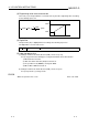
The processing block diagram of the S.OUT1 instruction is shown below.
(The numerals (1) to (6) in the diagram indicate the order of the processing.)
E1
BW
BB2
BB3
BB1
NMAX, NMIN
MVP
RUN(SPA 0)
STOP(SPA 1)
MAN
AND
AND
OR
BB4
AND
MV
MH, ML, DML
MODE
SPA
MHA
MLA
DMLA
TRKF
(1)
(2) (3) (4) (5)
(6)
(6)
AUT
or like
MAN or like
ERRI MHI
ERRI MLI
ERRI DMLI
Mode
judgment
Input addition
processing
Change rate,
upper/lower
limiter
Reset windup
Output
conversion
processing
Loop
stop
judgment
Alarm clear
processing
Loop stop
processing
Upper limit alarm
Lower limit alarm
Change rate alarm
All OFF
All OFF
Last BW