
User`s manual


8 - 2 8 - 2
MELSEC-Q
8 I/O CONTROL INSTRUCTIONS
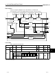
Block diagram
The processing block diagram of the S.IN instruction is shown below.
(The numerals (1) to (5) in the diagram indicate the order of the processing.)
AND
AND
OR
SPA
SEA
ERRI SEI
MODE
E1
BW
BB2
BB3
BB1
HH, H, L, LL NMAX, NMIN EMAX, EMIN
RUN(SPA 0)
STOP(SPA 1)
MAN
(1) (3)(2) (4)
(5)
(5)
Range check
Input limiter
Engineering
value reverse
conversion
Digital filter
Upper limit alarm
Lower
limit alarm
Loop stop
judgment
Loop stop
processing
Last BW
All OFF
Control data
Data specified in S.IN instruction
Specified position Symbol Name Recommended range
*1
Unit Data format
Standard
value
Store
Input data
S1
+0
+1
E1 Input value -999999 to 999999
Real number U
D1
+0
+1
BW Output value (-999999 to 999999) % Real number
S
BB
BB1 Alarm
BB2
Input upper
limit alarm
Block
memory
+2
BB3
Input lower
limit alarm
b15 b12 b8 b4 b0
B
B
3
B
B
2
B
B
1
(0: Without alarm)
(1: With alarm)
BIN
16bit
S
*1: The data of the item(s) where the values within the recommended range are given in the parentheses are stored by the system.
Users cannot set the data.
8