
User`s manual


3 - 2 3 - 2
MELSEC-Q
3 DATA USED FOR PROCESS CONTROL INSTRUCTIONS AND HOW TO
SPECIFY DATA
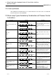
(b) Loop tag memory and operation constant locations in ladder diagram
Ladder diagram
The symbols in the ladder diagram mean the following.
Instruction name S.IN S.PHPL S.2PID S.OUT1
1) Input data head device R0 R20 R40 R60
2) Block memory head device R100 R120 R140 R160
3) Operation constant head device R200 R220 R240 R260
4) Loop tag memory head device R1000
Start contact
Instruction
name
1) 2) 3) 4) 5)
5) Set value head device R300
3
Loop tag memory (96 words)
Instruction
used
Item Data type
Standard
value setting
+0
+1
+3
+4
+10
+12
+14
+16
+18
+20
+22
+46
+48
+50
+52
+54
+56
+58
+60
+62
+64
+66
+90
+92
+94
S.PHPL
S.2PID
MODE
8
H
CT
Use name instruction common table.
T0
M0PLS
R0D0
FLT
R1000R200R100R0S.IN
R20R100EMOV
R1000R220R120R20
S.PHPL
R40R120EMOV
R300R1000R240R140S.2PID R40
R60R140EMOV
P1
K1
Execution command
P1CALL
T0
RST
FEND
T0
M0
Normal execution
R1000R260R160R60S.OUT1
D1R160
INT
Operation constant setting
RET
Loop tag memory setting
Real number
Real number
Real number
Real number
Real number
Real number
Real number
Real number
Real number
Real number
Real number
Real number
Real number
Real number
Real number
Real number
Real number
Real number
4000
H
4000
H
0.0
0.0
0.0
0.0
100.0
0.0
100.0
ALM
INH
PV
MV
SV
DV
MH
ML
RH
S.OUT1
S.2PID
S.2PID
S.OUT1
S.OUT1
S.PHPL
S.OUT1
S.2PID
S.2PID
S.2PID
S.2PID
S.2PID
S.2PID
S.OUT1
S.2PID
S.2PID
DML
DVL
P
I
D
GW
GG
MVP
1.0
100.0
100.0
1.0
10.0
0.0
0.0
1.0
0.0
0.0
1.0
0.0
0.0
0.0
Real number
Real number
Real number
BIN16bit
BIN16bit
BIN16bit
BIN16bit