
User`s manual


9 - 103 9 - 103
MELSEC-Q
9 CONTROL OPERATION INSTRUCTIONS
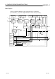
Block Diagram
The processing block diagram of the S. SEL instruction is shown below.
(The numerals (1) to (7) in the diagram indicate the order of the processing.)
BW
MHA
SPA
INH
OR
MAN
SLNO
RH, RL
(7)
PV, PV1 to PV2
(7)
BB1
BB2
MAN or like
RH, RL NMAX, NMIN MV TRK
(1) (2) (4)(3)
(5) (6)
(3)
MLA
MODE
DMLA
BB4
BB3
E1
E2
e1
Engineering
value
conversion
E1/E2
selection
processing
Mode check
Change rate,
upper/lower
limiter
Alarm output
processing
Alarm clear
All OFF
Loop
stop
judgment
RUN(SPA 0)
STOP(SPA 1)
Output
conversion
processing
Tracking
processing
All OFF
All OFF
Loop stop
processing